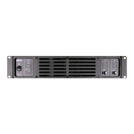
Ashly PE-3000 Betriebshandbuch - Seite 5
Blättern Sie online oder laden Sie pdf Betriebshandbuch für Verstärken Ashly PE-3000 herunter. Ashly PE-3000 13 Seiten. Pe series high performance professional power amplifiers
Auch für Ashly PE-3000: Technische Hinweise & Spezifikationen (2 seiten), Betriebshandbuch (13 seiten), Installations- und Benutzerhandbuch (2 seiten), Spezifikationsblatt (2 seiten)

Operator Manual – PE Series Amplifiers
Input Module
The PE-Series has been designed
with flexibility in mind. The input
section illustrated at right has been
engineered in modular form. All
amplifiers ship with the standard
input (shown) unless the Optional 32
bit/96kHz Protea
specified. This optional module
features both analog and digital
(AES/EBU) inputs, and two
additional processed output channels
to drive additional amplifier channels. Documentation for this module is provided in a separate
document. If there is an input feature or function you'd like to see developed for the PE-Series,
please contact Ashly.
1.
XLR/TRS Combo Balanced Inputs – These
connectors accept either a Male XLR or 1/4" TRS
plug.
2.
Channel Input Turnarounds – These connectors
provide signal to additional amplifiers via male XLR
jacks.
3.
Euroblock Connector Channel Inputs – These
connectors are in parallel with the Combo Inputs and
allow for signal connection using Euroblocks.
4.
Remote Level Control Connector – This connector
facilitates hard-wired remote attenuation control.*
5.
Remote Standby Connector – This connector
facilitates hard-wired remote on/off functionality.*
6.
Ethernet Connector & Indicators – This RJ45
Ethernet connector interfaces with a Protea NE
Installation
PE-Series amplifiers are designed for use in both fixed and mobile sound systems. Each
amplifier is shipped (unless otherwise specified) with the following factory settings:
Front panel:
On/Off Switch = Off
Attenuators = ∞
Before connecting to mains power, make sure that the switches are set to the configuration
needed for your particular application. Always switch the amplifier off before making any
changes to the settings. Failure to do so could result in damage to the unit or other components
in your system. Use four screws and washers when rack mounting the amplifier. For mobile use,
the unit should be secured using the rear rack mounting ears.
Requirements
PE-series amplifiers have specific physical, electrical and signal requirements for proper
operation. These requirements will vary depending on your specific application, setup, and the
settings on the amplifier. When setting up and testing your system, please take special care to
double check all connections and settings. Please refer to the specifications section of this
manual for specific input, output and other figures.
NE
DSP card is
All Rights Reserved
network, or computer if available. The indicators
show network link and data activity.
7.
Reset – This allows you to perform a factory reset to
return all parameters back to the factory defaults.
With the power off, insert a long thin lead (like a
paper clip) into the hole. Turn on the power and hold
in the switch. The signal LEDs on the front panel will
light in sequence (-15 to clip). When the sequence is
complete (about five seconds) and all signal LED's
illuminate simultaneously, the factory settings have
been restored.
*See the wiring diagram on page 11 for more
information.
Rear panel:
Input Ground Lift = Grounded
High Pass Filters (both Ch.) = Off
Mode Selector = Stereo
Clip Limiter = Off
Gain Selector = 32 dB
Page - 5
Introduction - 2
The PE Series - 3
Physical Description - 4
Front Panel
Rear Panel
Input Module
Installation – 5
Requirements
Typical Applications
Connectors & Polarity
Operation - 7
Troubleshooting - 8
Spec Table - 9
Measurements - 10
Dimensions - 11
Warranty - 12
