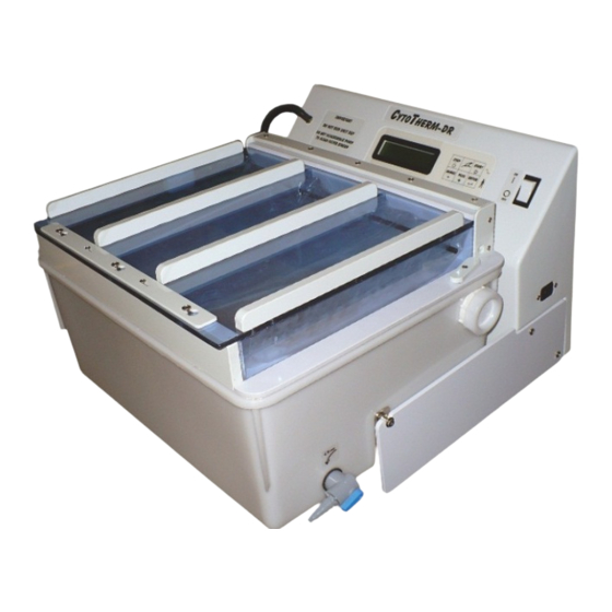
CytoTherm CT-DR Benutzerhandbuch - Seite 10
Blättern Sie online oder laden Sie pdf Benutzerhandbuch für Laborausrüstung CytoTherm CT-DR herunter. CytoTherm CT-DR 10 Seiten. Dry plasma thawing with rocking action

Rev 25 June 06 Fuse Table & TP1
Rev 5 June 04 add 3/4A slow blow fuse
to 12 Vac Xform lead. See D 467.
Fuse Amps
1 & 2
8
1 & 2
5
3
3/4
Power Cord
Filter
/Yel
Grn
Blu
Orn
Switch
High
Volt
Orn
Blu
Grn/Yel
120V xform
=MOV
Grn
5
Fuse-3
8
[12VAC]
~
Yel
4
Blu
Blu
3
2
Orn
[M]
Orn
1
240V xform
Grn
5
2
Fuse-3
8
[12VAC]
~
Yel
4
Blu
Red
3
2
Red
[M]
2
2
1
Orn
= 240V MOV
2
100V uses dual transformer.
see Dwg# 361
Wiring CT-DR / CT-4T
D 351B.kcw
File \Draw#\D#351.kcw Home
30 Nov 2000
1 Jul 02. 8A Fuses for 120/100
Rev B. 4 Jan 04
1. Add separate Neutral
wire from Bath Conn# 5 to
9- pin conn #8. Wire separate
neutral wires to heaters & pump.
2. Spade connectors on heaters.
3. CT-DR & 4T on one drwg.
100V units
4. Move heater wires to 1/4" spade
connectors from BATH connector.
5. Remove SWITCH conn. & solder
wires directly to board.
Ground is Green with Yellow stripe
&
Ground
Wire Nut
1/4" Spade
CONNECTOR to Flex Switch.
5
1
Vac
Type
120
Fast
240
Fast
12
Slow Blow
Brn=High V
Grn/Yel=Gnd
Blu=Neutral
Fuse-1
Fuse-2
1
+
GND
11
CT-4D Board
1
Blk
1
Blk
Rocking
Motor
1
Bath Section
Whi
9
8
Whi
Brn
7
5
3
4
Orn
2
Vio
1
Female Housing
Male Pins
Ground Pin (5)
is longer
10
3= NC
2
6
7
4
TP1
1
Strain Relief mounted on connector
Vio
9
Brn
Grn
8
7
Orn
Male Housing
5
Whi
Female Pins
3
4
Blu
2
Red
1
Level
Thermostat
Sensor
Safety
Screw
Orn
Orn Orn
Temperature
Brn
Sensor
Vio
Level
Thermistor
Sensor in
Rack
Mag. Sensor
Sensor
Connector
Level
Sensor in
Rack
Rack section
on CT-DR only.
Brn
Vio
Whi
Grn
Blu
Orn
Red
Blu
120/100V wired as shown
240V the 2 heaters are in series
Heater
Heater
Blk
120V
Pump
Blk
Blu
Blu
