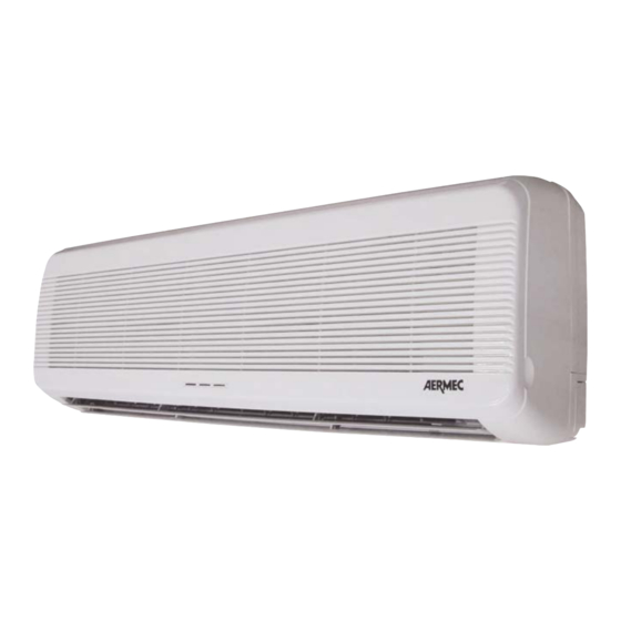
AERMEC FCW Series Installationsbroschüre - Seite 6
Blättern Sie online oder laden Sie pdf Installationsbroschüre für Heizgerät AERMEC FCW Series herunter. AERMEC FCW Series 19 Seiten. Fan coil

IMBALLO
I ventilconvettori vengono spediti con imballo standard in
cartone.
INSTALLAZIONE DELL'UNITÀ
ATTENZIONE: prima di effettuare qualsiasi intervento, assi-
curarsi che l'alimentazione elettrica sia disinserita.
ATTENZIONE: i collegamenti elettrici, l'installazione dei
ventilconvettori e dei loro accessori devono essere eseguiti
solo da soggetti in possesso dei requisiti tecnico-professio-
nali di abilitazione all'installazione, alla trasformazione,
all'ampliamento e alla manutenzione degli impianti ed in
grado di verificare gli stessi ai fini della sicurezza e della
funzionalità.
In particolare per i collegamenti elettrici si richiedono le
verifiche relative a :
- Misura della resistenza di isolamento dell'impianto elettrico.
- Prova della continuità dei conduttori di protezione.
LIMITI DI FUNZIONAMENTO
Massima temperatura di ingresso acqua
Massima pressione di esercizio
I ventilconvettori FCW vanno alimentati con tensione 230 V
(±10%) monofase a 50 Hz e collegamento a terra.
Se il ventilconvettore funziona in modo continuativo in raf-
freddamento all'interno di un ambiente con elevata umidità
relativa, si potrebbe avere formazione di condensa sulla
mandata dell'aria. Tale condensa, potrebbe depositarsi sul
pavimento e sugli eventuali oggetti sottostanti. Per evitare
fenomeni di condensazione sulla struttura esterna dell'appa-
recchio con ventilatore in funzione, la temperatura media
dell'acqua non deve essere inferiore ai limiti riportati nella
tabella sottostante, che dipendono dalle condizioni termo-
igrometriche dell'aria ambiente. I suddetti limiti si riferisco-
no al funzionamento con ventilatore in moto alla minima
velocità.
In caso di prolungata situazione con ventilatore spento e
passaggio di acqua fredda in batteria, è possibile la forma-
zione di condensa all'esterno dell'apparecchio, pertanto si
consiglia l'inserimento dell'accessorio valvola a tre vie.
Limiti di portata:
Water flow limits:
MOD.
Portata minima • Minimum water flow
Portata massima • Maximum water flow
MINIMA TEMPERATURA MEDIA ACQUA
MINIMUM AVERAGE WATER TEMPERATURE
Temperatura a bulbo umido
dell'aria ambiente °C
Wet bulb temperature °C
Al fine di evitare stratificazioni di aria nell'ambiente, ed
avere quindi una migliore miscelazione, si consiglia di non
alimentare il ventilconvettore con acqua più calda di 70°C.
L'uso di acqua con temperature elevate potrebbe provocare
scricchiolii dovuti alle diverse dilatazioni termiche degli
elementi (plastici e metallici), ciò comunque non provoca
danni all'unità se non si supera la massima temperatura di
esercizio.
Vengono qui riportate le indicazioni essenziali per una cor-
retta installazione delle apparecchiature.
Si lascia comunque all'esperienza dell'installatore il perfe-
zionamento di tutte le operazioni a seconda delle esigenze
specifiche.
Il ventilconvettore FCW deve essere installato in posizione
6
PACKING
The units are shipped in cardboard box standard packing
and polystirene shells.
UNIT INSTALLATION
IMPORTANT: check that the power supply is disconnected
before performing operations on the unit.
CAUTION: wiring connections installation of the fancoil
and relevant accessories should be performed by a techni-
cian who has the necessary technical and professional
expertise to install, modify, extend and maintain plants and
who is able to check the plants for the purposes of safety
and correct operation.
In the specific case of electrical connections, the following
must be checked:
- Measurement of the isolation resistance on the electrical
system.
- Testing of the continuity of protection conductors.
OPERATION LIMITS
80 [°C]
Maximum water inlet temperature
8 [bar]
Maximum working pressure
FCW fancoil power supply is 230 V (±10%) single phase at
50 Hz with earthing connection.
If the air conditioner works continuously on cooling mode insi-
de a room with high relative humidity, there might be the pro-
duction of condensate by air delivery of the indoor unit. The
condensate might collect on the object underneath or on the
floor.
To prevent the formation of condensation on the exterior of
the unit while the fan is operating, the average water tempe-
rature should not drop beneath the limits shown in the table
below, determined by the ambient conditions.
These limits refer to unit operation with fan at minimum
speed.
Note that condensation may form on the exterior of the unit
if cold water circulates through the coil while the fan is off
for prolonged periods of time, so it is advisable to fit the
additional three-way valve.
To avoid air stratification effects in the room and ensure
FCW 20
l/h
150
l/h
1150
Temperatura a bulbo secco dell'aria ambiente °C
21
23
15
3
17
3
19
3
21
6
23
-
improved mixing, do not exceed a fancoil water supply tem-
perature of 70°C. Use of water at higher temperatures could
cause "creaking" caused by various thermal expansion levels
of unit elements (plastic and metal), although this does not
damage the appliance if the maximum operating temperatu-
re is not exceeded.
This section specifies the procedures to ensure correct
installation of the appliance.
However correct final set-up is left to the experience of the
installer according to the specific requirements.
The FCW fancoil must be installed in a position that ensures
air distribution to the entire room. Ensure that there are no
obstacles (curtains or objects) to air transfer from the suction
grille (fig. 2). The unit must also be positioned to facilitate
FCW 30
200
1550
Dry bulb temperature °C
25
3
3
3
3
3
3
5
4
8
7
80 [°C]
8 [bar]
FCW 40
200
1550
27
29
3
3
3
3
3
3
3
3
6
5
31
3
3
3
3
5
