d&b audiotechnik Yi-SUB Handbuch - Seite 5
Blättern Sie online oder laden Sie pdf Handbuch für Subwoofer d&b audiotechnik Yi-SUB herunter. d&b audiotechnik Yi-SUB 11 Seiten.
2
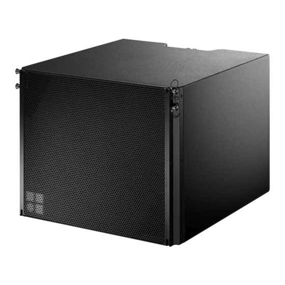
Yi-SUB loudspeaker
Yi-SUB loudspeaker
Cardioid dispersion pattern
Connector wiring
d&b Yi-SUB Manual 1.3 en
2.1 Product description
The Yi-SUB is a compact high performance cardioid subwoofer
designed to supplement the d&b Yi-Series cabinets.
The Yi-SUB houses two long excursion neodymium drivers in an
integrated cardioid setup: an 18" driver in a bass-reflex design
facing to the front and a 12" driver in a two chamber bandpass
design radiating to the rear. The arrangement and tuning provide a
cardioid dispersion pattern using a single amplifier channel.
The frequency response extends from 39 Hz to 140/110 Hz.
Cardioid dispersion
Cardioid dispersion avoids unwanted energy behind the system
and greatly reduces the reverberant field at low frequencies
providing highest accuracy in low frequency reproduction. The
subwoofers can be used as stand-alone solutions or in stacked
combinations with a minimum distance of 60 cm (2 ft) between
adjacent cabinets or between the cabinets and a side wall. When
set up in front of walls, the minimum distance to rear walls should
be 30 cm (1 ft).
Yi-Series rigging components and arrays
Cabinets are mechanically connected using the rigging strands on
both sides of the cabinet front and a central strand at the rear of
the cabinet. All necessary rigging components are mounted to the
cabinet and fold out or slide out when needed. The rigging
components are also intended to interconnect and secure Yi-SUB
cabinets in ground stacked applications.
A detailed description of the Yi-Series rigging components is given
in the Yi-Series Rigging manual which is provided with the
corresponding Yi Mounting frames.
A detailed description of planning and designing Yi arrays is given
in the technical information "TI 385 d&b Line array design,
ArrayCalc" which is provided with the Y Flying frame.
The d&b ArrayCalc simulation software can be downloaded from
the d&b website at www.dbaudio.com.
2.2 Connections
The cabinet is fitted with a pair of NL4 M connectors and a two
pole screw terminal block (ST). All four pins of both NL4 M
connectors are wired in parallel. The cabinet uses the pin
assignments 2+/2–. Pins 1+/1– are designated to full range
cabinets.
Pin equivalents of the applicable connector options are listed in the
table below.
NL4 M
1+
ST
n.a.
1–
2+
2–
n.a.
+
–
5