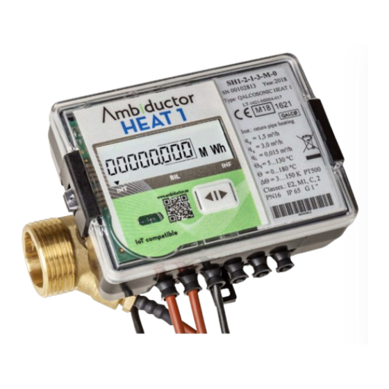
Ambiductor HEAT 1 Betriebs- und Montageanleitung Handbuch - Seite 13
Blättern Sie online oder laden Sie pdf Betriebs- und Montageanleitung Handbuch für Messgeräte Ambiductor HEAT 1 herunter. Ambiductor HEAT 1 20 Seiten.

Connections in the test / verification
mode
The 2-line 10-pole connection in the calculator, between the
terminals for the temperature sensors and the pulse in/out-
puts, activates the test / validation mode.
See picture.
In test mode, it is possible to achieve exact results at short
intervals.
To activate test / verification mode, jumper 3 must be mount-
ed (see Setting the Jumpers J).
Jumpers 1-5
Jumper 3 - activation of test mode
Do not turn off the meter in this position.
When jumper 3 is mounted, the unit assumes the test posi-
tion. "TEST" appears on the display, the calculation process
is stopped and all integrated parameter values are stored in
memory. After returning to normal mode, the original values
from before the test are displayed again.
The resolution of the measured values in the test / validation
mode as below.
Energy unit
kWh/MWh
Resolution,
000000,01 Wh
energy
Resolution,
volume
Ambiductor AB reserves the right to make changes without prior notice. Reprinting or copying this publication without permission is prosecuted.
GND
Tx - for reading in test mode
Energy pulses in test mode
Kommunikationskort
Volume pulses in test mode
Rx - for reading in test mode
Test mode on/off
Communication card
GJ
Gcal
0000000,1 kJ
0000000,1
kcal
00,000001 m
3
Pulse values in test / verification mode as below.
Permanent
Pulse va-
flow rate qp
lue volume
(l/p)
0,6
0,002
1,0
0,002
1,5
0,004
2,5
0,005
3,5
0,02
6,0
0,02
10
0,05
15
0,05
25
0,05
40
0,2
60
0,2
Exit test / validation mode
Remove jumper 3 to exit test mode and return to normal
mode. After leaving the test mode, previously saved values are
displayed.
Verification
Metrological control of the parameters of the heat meters is
performed according to the requirements specified in EN 1434-
5.
Overflow
At flow q <1.2 * qs (maximum flow) = linear flow.
At flow q> 1.2 * qs (maximum flow) = constant flow (q = 1.2
* qs is used for energy calculation). Error message 4 "Flow
rate higher than 1.2 * qs" is recorded and alarms all the time
it is active.
13
Pulse value energy
kWh/
GJ
MWh
0,1 Wh/p
0,5 kJ/p
0,1 kcal/p
0,2 Wh/p
1 kJ/p
0,2 kcal/p
0,2 Wh/p
1 kJ/p
0,2 kcal/p
0,5 Wh/p
2 kJ/p
0,5 kcal/p
1 Wh/p
5 kJ/p
1 kcal/p
1 Wh/p
5 kJ/p
1 kcal/p
2 Wh/p
10 kJ/p
2 kcal/p
5 Wh/p
20 kJ/p
5 kcal/p
5 Wh/p
20 kJ/p
5 kcal/p
10 Wh/p
50 kJ/p
10 kcal/p
10 Wh/p
50 kJ/p
10 kcal/p
Gcal
