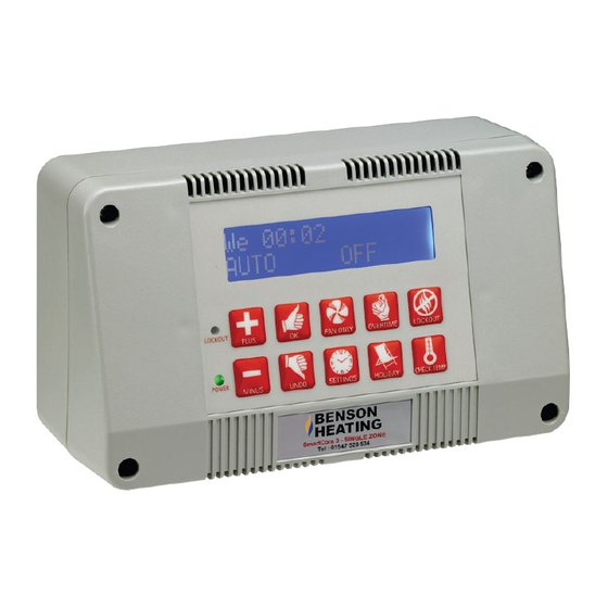
Ambirad SmartCom3 Boletín técnico - Página 3
Navegue en línea o descargue pdf Boletín técnico para Control Panel Ambirad SmartCom3. Ambirad SmartCom3 4 páginas. Control panel & nor-ray-vac radiant system
También para Ambirad SmartCom3: Manual (14 páginas), Cableado de instalación (8 páginas)
3. Instructions.
Before commencing any work ensure
that both the gas/oil and electricity
supplies are turned OFF.
1: Remove the four screws securing the original
controls panel to the heater, and withdraw to
reveal the interconnecting wiring.
2: Identify the four cables which run into the
heater (red, blue, black, grey). These should
already be connected to heater terminals 1,2,4
and 6 respectively.
3: Disconnect these four cables from the old
controls.
Wiring diagram
SC3-FM CONTROLLER
1
2
40
2
4
1
3
4: Connect cables to the new SmartCom FM
terminals as shown in the wiring diagram below.
5: Fit the new SmartCom FM to the heater using
the four screws provided in the kit.
6: Re-instate the gas/oil and electricity supplies.
7: Set up the new SmartCom FM if required
following the instructions in the supplied manual.
8: Test the heater for correct operation.
6
SMARTCOM TERMINALS
CABINET TERMINALS
5
6
LINK