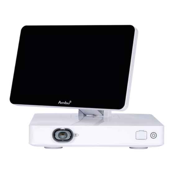
Ambu aBox 2 Manual de sustitución - Página 7
Navegue en línea o descargue pdf Manual de sustitución para Equipamiento médico Ambu aBox 2. Ambu aBox 2 16 páginas.

No.
Part
1
Touch Screen
VDI port (connector port for
2
specific Ambu visualization
devices)
3
USB 3.0 port (front)
4
USB cover
5
Power button
6
Base
7
Power cable
8
Wi-Fi antenna
9
Positioning arm
10
Video output ports (2 x DVI-D)
Video output ports (2 x
11
3G-SDI)
12
Wi-Fi antenna connector
13
USB 3.0 ports
14
LAN port
15
USB 2.0 ports
Trigger output ports (2 x 3.5
16
mm jack)
Trigger output ports (2 x
17
D-SUB9)
18
Power inlet
Connector for potential
19
equalization cable
1.5. Spare Parts
The spare parts may not be available in all countries. Please contact your local Ambu
representative.
CAUTIONS
•
To avoid malfunction of the equipment, only use spare parts supplied by Ambu. Do
not modify the spare parts.
Function
Displays the image from the Ambu visualization
device and the graphical user interface.
Connector port geometry and colour ensures
correct connection with compatible visualization
devices.
Enables connection of external USB flash drives.
Protects the front USB port.
Turns the power ON or switches to STAND-BY mode.
Contains the main unit.
Connects the displaying unit to a power outlet.
Connect Wi-Fi antenna to the displaying unit for
improved Wi-Fi signal.
Enables manual positioning of the touch screen.
The screen can be adjusted horizontally and
vertically as well as rotated.
Enable connection to external monitor or external
medical imaging recorder.
Enables connection of Wi-Fi antenna.
Enable connection of external USB flash drives.
Enables connection to ethernet.
Enable connection of external USB flash drives.
Enable connection to an external medical imaging
recorder to transfer trigger signals.
Enables connection to power cable.
Used for bonding of electrical products to eliminate
potential differences between conductive parts.
7
