Flomec G Series Manual del usuario - Página 3
Navegue en línea o descargue pdf Manual del usuario para Instrumentos de medida Flomec G Series. Flomec G Series 16 páginas. Industrial and chemical models
También para Flomec G Series: Manual del usuario del producto (20 páginas), Manual del usuario del producto (20 páginas)
This is extremely important when
sizing a turbine flowmeter where
the volume is measured per hour or
per day. For example, an application
where the total output is 500 barrels
per day, occurring in a 5 hour period;
the recommended turbine flowmeter
should be sized according to the
instantaneous flowrate:
(500 – 5) x 24 or 2,400 barrels per day
Thus, requiring an 1-½ inch turbine
flowmeter.
INSTALLATION
Turbine flowmeters are affected by
both upstream and downstream
process configurations. Turbine
flowmeters should always be installed
with a minimum of 10 pipe diameters
upstream and 5 pipe diameters
downstream. The only exception is
the placement of the pumps, valves,
etc., on the upstream end. When this
occurs, 20 diameters of straight pipe
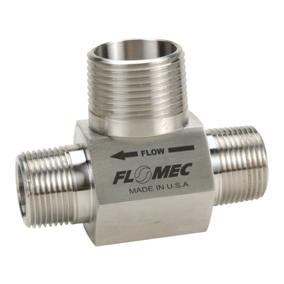
should be used. The direction of flow is
indicated by the arrow on the turbine.
All turbine flowmeters are designed
to measure flow in only one direction.
Check the items below once the
turbine flowmeter is installed in the
process line. This will ensure a suc-
cessful start-up.
1. Before installing the magnetic sen-
sor, make sure that it is functioning
properly. This can be accomplished
by checking the ohm resistance.
Refer to Checking Magnetic Pickup
in the Troubleshooting section.
2. If a magnetic pickup enclosure is
used on a sanitary turbine, discard
the seal cap that is included with the
unit. If no enclosure is used, install
the magnetic pickup and slip the
seal cap over the magnetic pickup
and threads on the adapter.
NOTE: This is not applicable for units
that use a low profile adapter.
921977-01C
3. Check the interconnection cable
between the turbine flowmeter and
readout device. Refer to Checking
the Cable Assembly section.
4. Make sure that the new or correct
K-factor is entered into the readout
device.
Initial Start-Up
Turbine flowmeters can be installed
in the horizontal or vertical position.
When installing a turbine flowmeter
in the vertical position, it is important
that the direction of flow be up through
the turbine flowmeter.
A spool should be installed in place
of the turbine flowmeter during initial
start-up of a new process line. The
process line should be purged, thus
eliminating any solids contained in
the line. Once this is completed, the
spool can be removed and the turbine
flowmeter installed.
Whenever possible, use 20 straight
pipe diameters upstream and down-
stream of the turbine flowmeter. The
length of straight pipe upstream and
downstream of the turbine flowmeter
can be reduced with the use of flow
straighteners or straightening vanes.
A minimum of 10 straight pipe diam-
eters upstream and 5 downstream
are required.
NOTE: Control valves should always
be installed downstream of the
turbine flowmeter.
The turbine flowmeter should be
installed in a location where the pro-
cess line will remain full of liquid at all
times. Otherwise, when the process
line becomes empty and a valve is
opened, the high velocity fluid hitting
the turbine flowmeter rotor can cause
severe damage.
When there is entrained air in the
process line, an air eliminator should
be used. This entrained air causes
air pockets and these air pockets
3