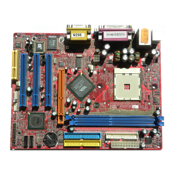
AMD VIA K8M800 Manual del usuario - Página 12
Navegue en línea o descargue pdf Manual del usuario para Placa base AMD VIA K8M800. AMD VIA K8M800 13 páginas. Chipset m/b for socket am2 64-bit dual core amd processor

(2) USB Port Headers (9-pin) :
USB2 / USB3
These headers are used for connecting the
additional USB port plug.
option USB cable, your can be provided with two
additional USB plugs affixed to the back panel.
(3) Speaker connector: SPEAK1
This 4-pin header connects to the case-mounted
speaker. See the figure below.
(4) Power LED: PWR LED1
The Power LED is light on while the system
power is on. Connect the Power LED from the
system case to this pin.
(5) IDE Activity LED: HD LED
This connector connects to the hard disk activity
indicator light on the case.
(6) Reset switch lead: RESET
This
2-pin
case-mounted reset switch for rebooting your
computer without having to turn off your power switch. This is a preferred method of
rebooting in order to prolong the lift of the system's power supply. See the figure
above.
(7) Power switch: PWR BTN
This 2-pin connector connects to the case-mounted power switch to power ON/OFF the
system.
(8) FAN Power Headers: SYSFAN1, SYSFAN2 (3-pin), CPUFAN (4-pin)
These connectors support cooling fans of 350mA (4.2 Watts) or less, depending on the
fan manufacturer, the wire and plug may be different. The red wire should be positive,
while the black should be ground. Connect the fan's plug to the board taking into
consideration the polarity of connector.
CPUFAN
4
1
SYSFAN2
SYSFAN1
3
1
FAN Power Headers
(9) CD Audio-In Headers (4-pin) : CDIN
CDIN are the connectors for CD-Audio Input signal.
Please connect it to CD-ROM CD-Audio output
connector.
By attaching an
connector
connects
3
1
USB2
Pin 1
Pin 1
Pin 1
to
the
10
USB3
Pin 1
USB Port Headers
PWRLED
JW FP
SPEAK
Pin 1
System Case Connections
CDIN
4
1
CD Audio-In Headers
