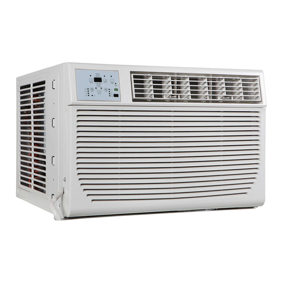
Coast-Air CEG-123A Manual de instrucciones de instalación y funcionamiento - Página 9
Navegue en línea o descargue pdf Manual de instrucciones de instalación y funcionamiento para Aire acondicionado Coast-Air CEG-123A. Coast-Air CEG-123A 17 páginas.

Installation and Operation Instruction Manual
INSTALLATION INSTRUCTIONS
Complete Installation:
1. Insert window sash seal behind the top of the lower window sash and
against the glass of the upper window (FIG.15).
2. Place the window-lock bracket on top of lower window and against upper
window sash on right side of the window (FIG.15).
3. Use a 3/32 drill bit to drill starter holes through the holes in the bracket
into the window sash (FIG.15).
4. Attach the window lock-bracket to the window sash with two #10 X 3/4
or or (1/2 )round-head screws to secure window in place (FIG.15).
5. Insert air conditioner into cabinet (FIG.16).
6. Insert front tabs of front panel into top of cabinet and swing front into place.
7. Attach bottom front of panel with front panel screws (FIG.17).
8. Plug into a grounded 3 prong outlet.
9. Press RESET on the power supply cord.
FIG.16
Through-the-Wall Cabinet Installation:
Option 1
wood, metal or plastic molding:
When using a wood, metal or plastic molding, the wood frame should line up with the inside wall as
Option 2
shown FIG.18
If the plastered wall is to be flush with the cabinet and no molding is used, the wood frame must be set
1/2 (13mm) into the inside wall FIG.19.
FIG.18
A B C
A. Molding
C. Wood frame
B. Inside wall
D. Louvers
Install Wood Frame:
1. Construct the wood frame. See FIG.20 for dimensions.
2. Measure the outside width and height of frame to determine wall opening dimensions. The wall
opening measurements should be :
Width : 22-5/8 (57.5 cm) plus twice thickness of wood used to build frame.
Height: 16 (40.6 cm) plus twice thickness of wood used to build frame.
Depth : 2-1/2 (6.4 cm) minimum to 6-1/2 (16.5 cm) maximum.
3. Cut the opening through the wall. Remove and save insulation.
4. Apply wood preservative to the outside exposed surface.
5. Insert the frame in the wall opening. Square and level frame.
6. Attach frame securely to the wall.
FIG.17
Plastered wall with no molding:
A B
C
D
A. Plastered wall
B. Inside wall
FIG.19
A
D
C. Wood thickness
C. Wood frame
D. Louvers
9
CEG-81A & CEG-123A
FIG.15
B
C
A
D
A. Window lock bracket
B. Upper window glass
C. Window sash seal
D. #10X3/4 or or (1/2 )
round-head screws
FIG.20
C
B
D
C
www.coastair-ac.com
