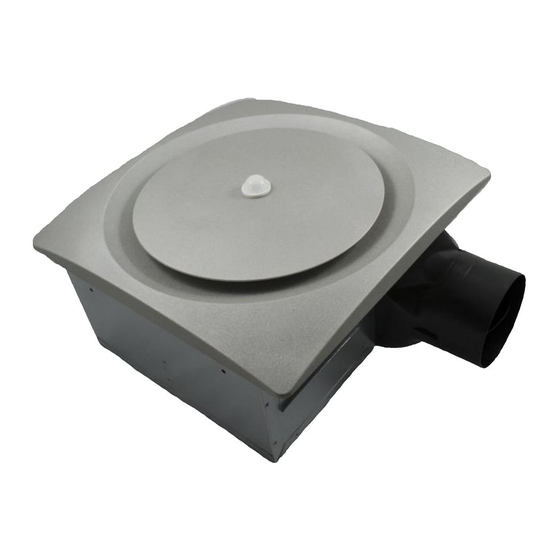
aero pure VSF110DMH-S Manual de instalación - Página 3
Navegue en línea o descargue pdf Manual de instalación para Ventilador aero pure VSF110DMH-S. aero pure VSF110DMH-S 4 páginas. Bathroom fan

ASSEMBLY INSTRUCTIONS
2. Mount with mounting holes and hanger bar
Slide one hanger bar into the channel on the housing and adjust as
needed to fit between framing. Hold housing in place so that the
housing contacts the bottom of the joist. Screw housing to joist through
the hole A and hole B. Screw the hanger bar onto the other side of joist
through the hole (refer to diagram at right).
Screw hanger bar to housing with screw A.
Hanger Bar Options
Distance A
13 1/4 in to 15 1/2 in (336mm-394mm)
16 1/2 in to 18 7/8 in (419mm-480mm) Hanger bar (long)
3. Mount with hanger bars only
Slide hangar bars onto housing and adjust as need to fit between
framing. Extend the hanger bars to the width of the framing. Position
the fan with the hanger bar tabs wrapped around the bottom edge of
the framing, holding the fan in place. Secure hanger bars to framing
using one screw on each end of hanger bar (refer to diagram at right).
Screw hanger bar to housing with screw A.
Hanger Bar A Option
Distance A
14 in to 23 1/2 in (356mm-597mm)
21 1/4 in to 23 1/2 in (540mm-597mm)
4. Mount to I-joist
Slide one hanger bar (long) into channel B on the housing and adjust
as needed to fit between framing. Hold housing in place so that the
housing contacts the bottom of the joist. Screw housing to joist
through hole D and hole C. Screw the hangar bar onto the other side
of joist through the hole (refer to diagram at right). Screw hangar bar
to housing with screw A.
5. INSTALL ROUND DUCTWORK
Connect the round ductwork (not included) to the damper/duct connector,
and run the ductwork to a roof or wall cap (not included). Using duct tape
(not included), secure all the ductwork connections so that they are air
tight. Insulated flexible duct is recommended for the quietest possible
installation. A 1 – 3 foot run of rigid duct- followed by insulated flexible
duct- will ensure quietest operation.
CONNECT ELECTRICAL WIRING
Run 120 V AC house wiring to the location of the fan. Use only UL-approved connectors (not included) to attach the house wiring to
the wiring plate. Refer to the wiring diagram, and connect the wires as shown.
FAN
BLK
SWITCH
BLK
WHT
LINE
WHT
IN
GRD
SWITCH BOX
Hanger Bar
Channel
Hanger bar (short)
Channel A (Fig. 1)
Channel B (Fig. 2)
Hanger Bar A
Hanger bar (short)
Hanger bar (long)
FAN
Fan
Delay time
Preset switch
H
Sensor
Humidity
Sensor Switch
CONTROL
N
CIRCUIT
UNIT
Screw A
Screw A
Fig. 1
Screw A
Screw B
BLACK(BLK)
BROWN(BRN)
FAN
SWITCH BOX
120V AC LINE IN
3
Screw B
Screw A
Screw B
Screw A
Fig. 2
Screw A
Hanger bar A
Hanger bar (long)
Screw A
WHITE (WHT)
GROUND (GRD)
WIRE PANEL
UNIT
RECEPTACLE
VSF110DMH-S
