Barksdale Dynalco SST7400 Manual de instalación y funcionamiento - Página 11
Navegue en línea o descargue pdf Manual de instalación y funcionamiento para Interruptor Barksdale Dynalco SST7400. Barksdale Dynalco SST7400 19 páginas. Speed switch / transmitter
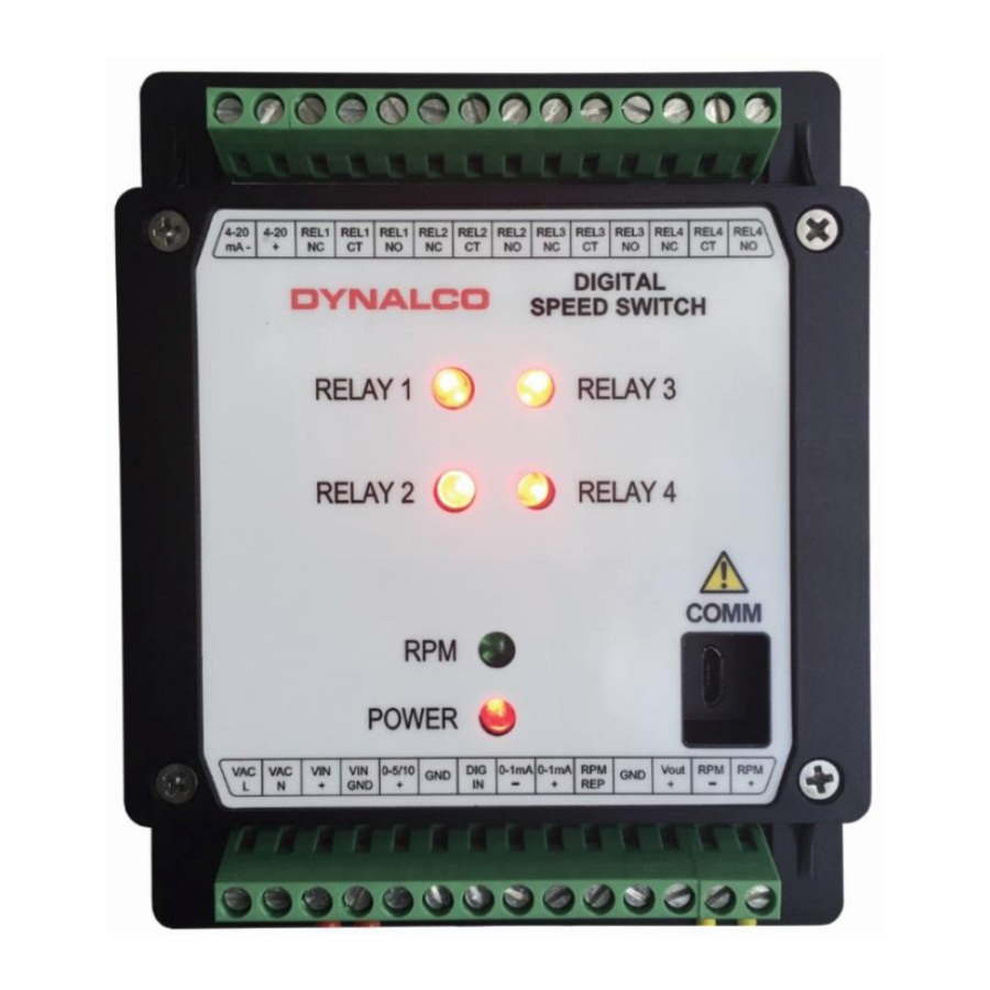
RPM Signal
The RPM Signal needs to be programmed prior to all other settings.
The SST7200 & SST7400 are capable of accepting input signals from 2-wire (also known as
variable reluctance) magnetic pickups as well as 3-wire (powered, TTL or hall-effect) type
sensors. The output from 2-wire pickups is an AC signal where the 3-wire type will normally
have a positive-going (non zero-crossing) square wave output.
Gear Teeth
o Required to convert RPM to Hz for
proper calibration
Sensitivity Level
o Set for Med-High for most applications
o Higher
sensitivity if needed for low speed
applications
o Lower level will be less sensitive to
noise
Max Wave Duration
o The Max Wave Duration is defined as the maximum time allowed between input
signal pulses before a sensor fault is declared. For example, a shaft with 2
keyways turning at 0 – 10 RPM would have an extremely low frequency range,
calibrated below:
Frequency
Then, the period (time in seconds between pulses) is calculated as:
Period
In this example, the pulses would be received in time intervals of once every 3
seconds or longer. The Max Wave Duration can be configured to a maximum
value of 10,000 milliseconds (10 seconds) to allow for this low speed range.
Any pulse not received within 10 seconds would be considered a sensor fault.
o Note that the default value of 1000 Milliseconds (1 second) is correct for most
applications.
level
will
allow
= RPM X # teeth / 60
= 10 X 2 / 60 = 0.333 Hz
= 1 / Frequency
= 1 / 0.333 = 3 seconds
greater
10