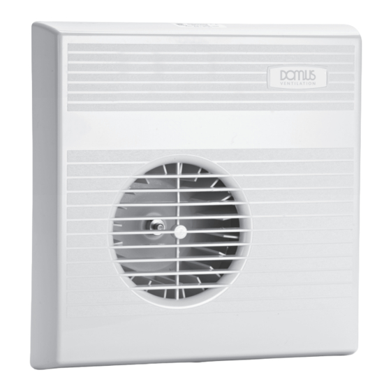
Domus MTT 070B Instrucciones de instalación - Página 4
Navegue en línea o descargue pdf Instrucciones de instalación para Ventilador Domus MTT 070B. Domus MTT 070B 4 páginas. Mayfair wall/ceiling fan

Product Function Guide
Single Speed
MSS 070B.
Single speed fans requiring external switching.
Single Speed
MPC 070B.
with pull/cord
Single speed fans with integral pull-cord switch.
switch
Single Speed
MTD 070B.
with time delay
Single speed fan with integral adjustable timer.
Normally operated via light switch.
Twin Speed
MTS 070B, MTS 100B
Twin speed fans designed to run on slow speed when room is unoccupied and on high
speed when room is occupied.
Normally operated via light switch.
Twin Speed
MTT 070B.
with time delay
Twin speed fans designed to run on slow speed when room is unoccupied and on high
speed when room is occupied. This product has an adjustable overrun timer that allows the
fan to run on high speed for a set time after the room has been vacated. Normally operated
via light switch.
Single Speed
MCC 070B.
with condensation
Adjustable condensation control turns fan on automatically when
control and
humidity reaches a preset level and off when humidity drops
time delay
below that level. When not operating on humidity the fan functions at the single speed with
time delay. Manual operation is normally via the light switch.
Twin Speed
MCT 070B.
with time delay/
Adjustable condensation control switches onto slow speed
condensation control
when humidity reaches a preset level and off when humidity drops
for remote switching
below that level. The fan can be switched onto high speed (boost)
with additional
using a remote switch (normally via a light switch). When the high
pull-cord boost
speed is turned off an adjustable timer keeps the fan running on high speed for a preset
time. Alternatively the fan can be switched on to high speed using the integral pullcord
switch. The pullcord switch works independently from the remote switch. When either the
remote switch or pullcord switch is operated a red indicator is illuminated.
Single Speed
MIR 070B.
infra red control
These fans are operated by a passive infra-red sensor detecting
(P.I.R.)
movement. The range of the sensor is about 5 metres with an operational arc of 15 degrees
from the centre of the sensor. The control unit features an adjustable timer. This allows the
fan to run for a preset time after the last movement within the range of the sensor has been
detected. Important: Passive infra red operated fans must not be installed above a
heater or radiator.
ELECTRICAL SUPPLY
230V ac ~ 50HZ
MODEL
070
SLOW SPEED
HIGH SPEED
20W
35W
Installation using building-in frame - May 905B
WALL MOUNTED
In the chosen position (as high on the wall as possible) cut a hole through the wall to take a 100mm duct for the fan
discharge. This should slope downwards towards the outside to allow for condensation drainage.
When this is done, position the building-in frame with the discharge outlet at the top right over the duct hole. Mark
around the frame and cut an aperture to take the frame and fan. It is important that the front edge of the frame is flush
with the surface of the wall.
If fitting in a solid wall the aperture should be at least 115mm deep. If installing in a cavity wall with loose thermal
insulation you will need to make a cavity liner.
When all the cutting is done, grout the frame into position making sure that the front edge of the frame is flush with
the wall. When the frame is in position, fit the discharge duct into position from the outside and trim to length. Before
grouting into position, seal the duct to the building-in frame spigot. When duct is in position fit discharge grille.
While fitting the building-in frame, provision must be made for the power supply cable.
To fit the fan, first remove the front cover, this is retained by a screw on the bottom edge. Enter the electrical contact
pins and discharge into their sockets and push gently into position. Retain fan with the four 6mm screws supplied.
Refit front cover.
CEILING MOUNTED
Select a suitable position on ceiling for fan. Ensure that the chosen position is between and square to the roof joists. Using
the building-in frame as a template, mark and cut out the square hole to fit the frame into. Cut and fit two noggins to fit
between the joists. Position them alongside the frame aperture so they will support the frame when it is in position. Fit the
frame into position ensuring the front edge is flush with the ceiling surface. Secure firmly by screwing through the holes in
the side of the frame into the joists or noggins.
The discharge from the fan may be ducted through a roof cowl or through the eaves. If ducting through a cowl, provision
must be made for condensation drainage. A condensation trap can be made from flexible ducting as illustrated or you may
use a purpose made product.
If discharge is to exit through the eaves, the duct must slope downwards towards the outside to allow for condensation
drainage. To ensure maximum efficiency from the fan, flexible ducting and bends must be kept to a minimum.
To fit the fan first remove the front cover. This is retained by a screw on the bottom edge. Enter the electrical contact pins
and discharge into their sockets and push gently into position. Retain fan with the four 6mm screws supplied and refit the
front cover.
