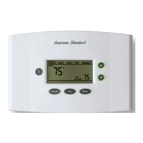
American Standard ACONT402AN32DA Manual del instalador - Página 4
Navegue en línea o descargue pdf Manual del instalador para Termostato American Standard ACONT402AN32DA. American Standard ACONT402AN32DA 18 páginas.

Press Fan to return to the previous step.
Use the Up and Down arrow buttons to select or change
setup options.
Lock - Unlocok Keypad:
Press and hold Up Arrow and Down Arrow at the same
time.
("Keypad Locked" will display on LCD screen)
Defeat Equipment Time Delay:
(Current Cycle only) Press Mode and Down Arrow at the
same time.
Checkout
There are two methods of verifying that the Comfort
Control operates the system as intended.
Method 1: Normal Mode
This can be accomplished by pressing the appropriate
keypad button(s) to cycle the system through each of
the available modes and increasing or decreasing the
setpoint to activate and deactivate the cycle.
The minimum on and off cycle time delays, selected
during the setup, will be enforced. Press the appropri-
ate keypad button for the filter timer, outdoor tem-
perature display and energy savings features to verify
they are set to the end user's desired preference.
Method 2: Manual Test Mode
The Comfort Control's load outputs can be verified
using the manual test mode. See Table 1 for navigat-
ing through the manual test mode steps.
To Enter The Manual Test Mode:
1.) Set System Mode to OFF
2.) Set Fan to AUTO
3.) Press and hold Mode and Down Arrow at the same
time.
The Manual test mode will time out and return to normal
operation after 4 minutes from the last key press.
NOTE: The manual test mode allows the installer to ener-
gize the G fan relay, Table 1, Step 70, and then advance to
Step 72 to energize the Y compressor output with the fan
still operating. It is recommended that this method be used
to prevent damage to the compressor.
RESISTANCE
T deg F
(OHMS X 1000)
10K THERMISTOR
-15
138.9
-10
117.7
-5
99.9
0
85.1
5
72.7
10
62.3
15
53.5
20
46.1
25
39.8
30
34.5
4
Table 2
RESISTANCE
T deg F
(OHMS X 1000)
10K THERMISTOR
35
30.0
40
26.1
45
22.7
50
19.9
55
17.4
60
15.3
65
13.5
70
11.9
75
10.5
Installer's Guide
Table 1
Manual Test Mode
Menu Item
Default
(Press Mode or Fan)
G - Fan Relay
Off
On / Off
BK - BK Output
35%
35% - 100%
Y1 - Compressor
Off
On / Off
(G - must be ON)
Y2 - Compressor
Contactor
Off
On / Off
(G - must be ON)
O - Switch Over
Ht
CL / Ht
Valve
W1 - Heating Relay
Off
On / Off
W2 - Heating Relay
Off
On / Off
W3 - Heating Relay
Off
On / Off
"SC"
All Icons On (see fig 8)
LCD
--
All Icons Off
Press and hold MODE to advance to
Factory Use Only
step 80 and press "$" to exit
Figure 8
RESISTANCE
T deg F
(OHMS X 1000)
10K THERMISTOR
80
9.3
85
8.3
90
7.3
95
6.5
100
5.8
105
5.2
110
4.7
115
4.2
120
3.8
Setting (Choices)
Step
(Press Up or Down
(Press Mode or Fan)
Arrow)
"6"
70
71
"y"
72
"y2"
73
"O"
74
'U1"
75
'U2"
76
"U3"
77
78
79-89
Pub. No. 11-HD03D3-3
