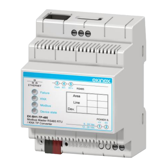
Ekinex EK-BH1-TP-485 Manual - Página 3
Navegue en línea o descargue pdf Manual para Pasarela Ekinex EK-BH1-TP-485. Ekinex EK-BH1-TP-485 4 páginas. Gateway modbus master rtu rs485 - knx tp

voltages, both DC and AC.
Vmin
Vac
Vdc
ETHERNET
Failure
KNX
Modbus
Device state
EK-BH1-TP-485
Modbus Master RS485 RTU
/ KNX TP Converter
+
Alimentazione
-
Important! In case of DC power supply, DO NOT
reverse the terminal blocks polarity!
KNX connection
Connection to KNX bus is made via the supplied KNX
terminal block. The terminal block must be inserted into
the slot located on the lower front side of the device.
KNX terminal block features
•
Conductors' spring clamping
•
4 conductors' location for each polarity
•
Suitable for KNX bus cables with single-wire
conductors (diameter between 0.6 and 0.8 mm)
•
Recommended wire stripping: 5 mm
•
Color code: red = bus conductor + (positive), black =
bus conductor – (negative)
ETHERNET
EK-BH1-TP-485
Modbus Master RS485 RTU
/ KNX TP Converter
Bus
+
KNX
-
Vmax
8
24
12
35
3
4
5
Com
RT-
RT+
RS485
Area
Line
Dev.
POWER S.
+V
0V
8...24 Vac
1
2
12...35 Vdc
3
4
5
Com
RT-
RT+
RS485
Failure
Area
KNX
Line
Modbus
Dev.
Device state
POWER S.
+V
0V
8...24 Vac
1
2
12...35 Vdc
RS485 Modbus connection
RT+
RT-
Com
In order to terminate the RS485 network and balance the
line impedance, you must enter the terminating resistor
(120 Ω), by setting ON the 1-way microswitch B.
The maximum extension of the RS485 network is 1200
m.
Below are some recommended cable codes for wiring
the RS485 line:
•
Belden code 8132. 2x 28AWG twisted pairs of
conductors + foil shielding + shielding mesh;
•
Belden code 82842. 2x 24AWG twisted pairs of
conductors + foil shielding + shielding mesh;
•
Tasker code C521. 1x 24AWG twisted wire pair + foil
shielding + shielding mesh;
•
Tasker code C522. 2x 24AWG twisted pairs of
conductors + foil shielding + shielding mesh.
Configuration and commissioning
Configuration and commissioning of the ekinex®
gateway must be performed using the application
program CGEKBH1TP485, available for download at
www.ekinex.com.
System requirements for configuration software
•
Desktop o laptop PC with Ethernet IEEE 802.3 port.
•
32/64 bit operating system, Microsoft Windows® XP,
7, 8.0, 8.1 e 10.
Note. .NET Framework 4.0 system library installation is
required.
The ekinex® configuration software CG-EK-BH1-TP-485
allows you to perform the following operations:
•
Selection of physical parameters of the RS485 serial
communication;
•
Selection of physical address of the device over the
KNX TP network;
•
Selection of Ethernet parameters (for configuration
download only);
•
KNX network: communication objects definition and
relative
group
communication objects definition and relative group
addresses to be sent over the KNX network;
Pag. 3
3
4
5
ETHERNET
Com
RT-
RT+
RS485
Failure
Area
KNX
Line
Modbus
Dev.
Device state
POWER S.
EK-BH1-TP-485
+V
0V
Modbus Master RS485 RTU
8...24 Vac
1
2
/ KNX TP Converter
12...35 Vdc
addresses
to
be
acquired;
