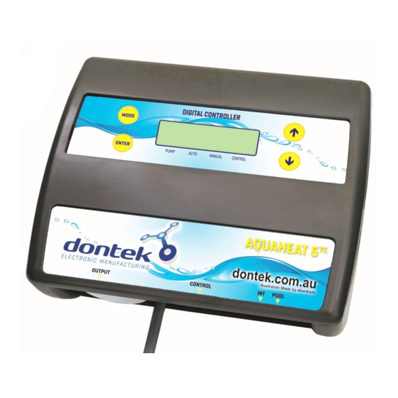
Dontek AQUAHEAT H5TC Manual de instrucciones - Página 2
Navegue en línea o descargue pdf Manual de instrucciones para Controlador Dontek AQUAHEAT H5TC. Dontek AQUAHEAT H5TC 4 páginas.

INSTALLATION INSTRUCTIONS
THIS APPLIANCE IS NOT INTENDED FOR USE BY
YOUNG CHILDREN OR INFIRM PERSONS WITHOUT
SUPERVISION. PLEASE ENSURE THAT YOUNG
CHILDREN ARE SUPERVISED TO ENSURE THAT
THEY DO NOT PLAY WITH THE APPLIANCE.
CONTROLLER MOUNTING
Find a suitable location to mount the control box.
Ideally, as with all pool equipment, it should be
installed out of direct weather and no closer than
3 metres from the water's edge and a minimum
600mm above ground. The power cable is 1.8m
long and should be plugged directly into a
general power outlet, not into an extension lead.
Fix the mounting bracket to a solid structure
via screws and wall plugs kit provided, and
slide the controller on, locking into place.
Adjusting screws on the back of unit to ensure
snug fit
To remove unit, lift and gently pull away from
structure.
PUMP CONNECTIONS
The pool circulating pump plugs into the 240V
socket labelled PUMP.
SANITISER CONNECTION
The sanitiser (Ioniser, Chlorinator or Ozoniser
etc.) connects directly into a general power
outlet, not into an extension lead. Plug the Black
power lead from H5TC into the sanitiser. Set the
sanitiser to operate for the required filtration and
dosing requirements.
AQUAHEAT H5TC v1.0
POOL SENSOR
The pool sensor must be fitted into the heating
circuit, as close to the pool as practical,
preferably in a position out of direct sunlight. It is
recommended that a 14.5mm hole be drilled into
the side of the PVC pipe (not the top of the pipe
where water will collect). This can be carried out
using a Dontek PD01 grinding drill or a small pilot
hole can be drilled with a 14.0mm drill-bit used
spinning in a counter clockwise direction to
minimize the chance of shattering pipe. Insert
the grommet into the pipe and gently push in the
sensor barb. Ideally ~30cm of the cable from the
sensor should be tied to the shaded side of the
pipe to prevent extreme ambient conditions
leeching into the sensor via the copper in the
cable. The blue sensor plug is to be fitted to the
plug socket marked POOL.
HEATER:
Connect the heater cable from the controller
output marked HEATER to the heaters flow or
pressure switch. Check with heater manufacturer
for correct interlocking procedure. See picture
for typical connection set-up. Note damage
caused by incorrect connections will void
warranties.
Internal connection to pool heater (check with
heater manufacturer).
2
