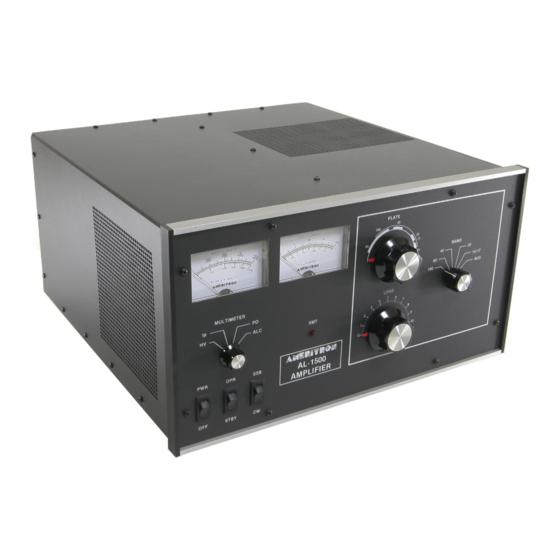
AMERITRON AL-1500 Manual de instrucciones - Página 6
Navegue en línea o descargue pdf Manual de instrucciones para Amplificador AMERITRON AL-1500. AMERITRON AL-1500 16 páginas. Full power linear amplifier

TRANSFORMER INSTALLATION Cont.
For 240V Operation (factory wired):
The four primary leads have colored plastic insulating boots
over the quick disconnect terminals. Slide these back prior to
installing the leads. !nstall the color coded boots as
follows:(see Fig. 1) Note: Japanese export model (AL-1500J)
should follow the 240V operation steps to properly connect
their transformers. The AL-1500J is supplied with a special
transformer for 200V operation.
1. BLUE (Brown wire) to the top relay terminal
2. YELLOW (Black/White) to the top terminal of terminal
block
3. CLEAR (Black wire) to the second terminal of terminal
block
4. RED (Brn/Wht) to the bottom terminal of terminal block
Now slide the colored insulating boots back over the ter-
minals. Note: The green wire is not used for 240V operation.
There is no green wire on the AL-1500J export model
transformer.
Important: The leads must be in the positions indicated by
the color coded insulating boots(see Fig. 1) for 240V opera-
tion. Or for 200V operation in Japan. Caution: Do not use
the 220V wiring unless the line voltage is always below 220
VAC. The Standard USA voltage is 240 VAC, not 220.
For 220V operation (see Fig. 3), follow the first three steps
above, then follow the steps below:
1. Slide the RED boot back on the BRN/WHT
wire.
2. Clip the terminal connector off the wire and slide
the RED boot off.
3. Remove the restraint from the GRN wire and
slide the RED boot on to the wire.
4- Solder the terminal connector to the GRN wire.
5. Tape up the BRN/WHT wire because it will
not be used.
TUBE INSTALLATION
Note that one of the tube pins is larger in diameter. This
larger pin "keys" the tube base and socket. Install the tube by
aligning the tube pins with the socket contact terminals, then
seat the tube with vertical pressure ONLY. Do not "rock" or
"twist" the tube. Also the chimney is already mounted inside
the AL-1500 amplifier.
After the tube is installed, attach the anode connector as
follows: (Refer to the Fig. 4)
. Remove screw "A" that holds the anode con-
nector to the 500pf blocking capacitors.
2. Attach the anode connector to the tube anode.
3. Insert screw "A" into the 500pf capacitors and
snug it down.
5
Fig. 3
Fig. 4
Top View of 1500 Tube
