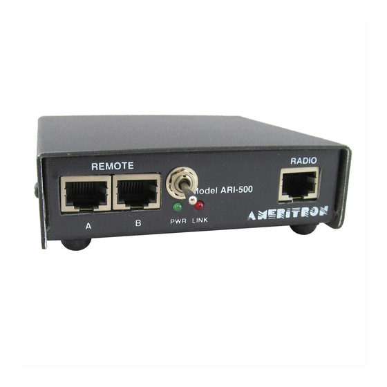
AMERITRON ARI-500 Manual de instrucciones - Página 5
Navegue en línea o descargue pdf Manual de instrucciones para Interruptor AMERITRON ARI-500. AMERITRON ARI-500 13 páginas. Automatic band switch for the ameritron als-500m; ameritron als-600 amplifiers
También para AMERITRON ARI-500: Manual de instrucciones (16 páginas)

ARI-500 Automatic Band Switch for ALS-500/600
Interfacing to Yaesu Radios
Yaesu radios output band information using a 4-line BCD format. The band data lines are found on the BAND DATA connector or
LINEAR port on most Yaesu radios. Some Yaesu radios share the CAT port with the LINEAR port. The radio must be configured so
that the port is in LINEAR mode or the band data information will not be sent to the ARI-500. Check your radio's manual to
determine the proper configuration of the LINEAR port. The diagrams below show popular Yaesu connections to the ARI-500.
Double check your radio's manual to ensure the correct Band Data connections. Please note that Pin 8 on the Yaesu connector (TX-
INH) must be connected to ground, Pin 3 on the FT-MP/2000/9000 series of radios. This connection is optional on the FT-
857/897/100 radios.
Yaesu FT-857/897
Linear Port
BCD B
BCD D
8
Rear View of
Yaesu Transceiver
5
2
Yaesu FT-100D
Linear Port
Gnd
Rear View of
Yaesu Transceiver
BCD C
TX Gnd
BandA
BandB
2
4
5
1
6
7
8
Connection
Band Data A
Band Data B
Band Data C
Band Data D
Amp Key / TX GND
Ground
Instruction Manual
ARI-500
7
6
12345678
1
Radio Input
ARI-500
BCD A
TX Gnd
BCD B
12345678
Radio Input
BCD D
BandC
GND
3
Linear
BandD
Yaesu MP/2K/9K Cabling
ARI-500 Radio Input
Pin 7
Pin 6
Pin 5
Pin 4
Pin 2
Pin 1
Rear View of
ARI-500
Rear View of
ARI-500
1 2 3 4 5 6 7 8
Yaesu Linear Socket
Pin 4
Pin 5
Pin 6
Pin 7
Pin 2
Pin 3/8
5
