AMERITRON RCS-12 Manual de instrucciones - Página 4
Navegue en línea o descargue pdf Manual de instrucciones para Interruptor AMERITRON RCS-12. AMERITRON RCS-12 16 páginas. Automatic antenna switch

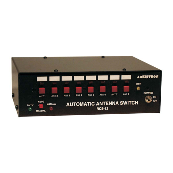
Ameritron RCS-12 Instruction Manual
Automatic Antenna Switch
Overview
Band Data Information
The RCS-12 will operate with simple push-button operation in Manual mode. In Automatic mode, the
RCS-12 reads Band Output Data from the appropriate jack on the back of your transceiver(s). The RCS-
12 is designed to work with most Icom, Yaesu, and Kenwood transceivers. There are separate inputs for
each of these input types. Please read this manual carefully, because some older models of transceivers
may have a different output format than newer ones.
New Kenwoods: This category is for new Kenwoods that have a DB-9 connector for computer control.
Serial data is read from this port to get the band data.
Icom: Icom transceivers use a "step voltage" to output band data. A voltage from 0 - 8 Volts is output
from the band data pin on the accessory jack.
Yaesu, older Kenwoods, and others: This category will cover most radios besides Icoms and newer
Kenwoods. Yaesu outputs band data in a 4 line BCD format. Many other transceivers use this standard.
The RCS-12 does not actually care what binary number the BCD data represents, it will match the
"pattern" with whichever antenna you preset it to.
If your transceiver is not one of the above listed, please check in your instruction manual to see if it has a
BCD output that is similar to that of Yaesu.
Also note that sometimes the same output will be used for more than 1 band. For example, Icom uses the
same output for 15 and 17 meters, and 10 and 12 meters.
Hot Switch Protection
The RCS-12 will fully protect your transmitter and antenna system from hot switching. This feature will
prohibit you from switching antennas while your transmitter/amplifier is transmitting. Hot Switch
protection is very useful during contesting ,when antennas may need to be switched often. This feature
also includes a user programmable delay that will allow sufficient switching time for the tower-mounted
relays that you are using. This delay can be programmed from 10ms to 1s, default 50ms. See page 10 for
more details. The hot switch protection sequence works as follows, assuming an antenna has already
been selected.
Transmit, unkey→ Delay 10ms→ Select Antenna → Relay Switching Delay (10ms – 1s) → Transmit Again
2
