bolid SIGNAL-20M Manual de instrucciones
Navegue en línea o descargue pdf Manual de instrucciones para Sistema de seguridad bolid SIGNAL-20M. bolid SIGNAL-20M 4 páginas. Intrusion and fire alarm control panel
ISO 9001
1
GENERAL INFORMATION
1.1
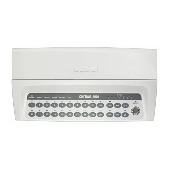
The Signal-20M Intrusion and Fire Alarm Panel (hereinafter referred to as Panel) is intended for use as a combined device to
monitor and control alarms in the following systems:
–
Fire alarm and extinguishing systems
–
Evacuation and alarm system of Type 1 and Type 2
–
Intrusion detection and panic alarm system
–
Auxiliary alarm systems
1.2
The Signal-20M supports conventional (nonaddressable) threshold wire-connected detectors.
1.3
The Signal-20M can operate as a processing module of rate-of-rise heat detectors and supports sensing elements (thermal cables)
detecting temperature threshold exceedance.
1.4
The Signal-20M automatically monitors communication lines with detectors, call points and actuating devices of fire protection
systems.
1.5
The panel is not a scalable system.
1.6
The panel supports connection to PC for control and programming functions.
1.7
The panel is designed for 24\7 continuous operation
1.8
The panel is a reparable device with periodic maintenance
1.9
The Panel is not designed for the use in aggressive, dust, explosive and fire-hazardous environments.
2
SPECIFICATIONS
No
2.1
DC supply voltage, V
Consumption current, mA, no more *
- in 'Quiescent' mode
2.2
- in 'Fire' mode
* excluding current consumption of alarm devices
2.3
Power inputs
2.4
Startup time, s
2.5
Inputs
2.6
Voltage on unloaded input terminals, V
Input short-circuit current limitation, not more than, mA
2.7
Resistance of input terminal resistor, kΩ
2.8
Max. current consumption of all detectors in standby mode, mA
- Type 1 (Fire smoke) inputs
2.9
- Type 2 (Fire combined) inputs
Input resistance in various states
2.10
Maximum allowable resistance of the sensing element of a linear heat detector (thermal
2.11
cable), kΩ
Input communication line:
- max. wire resistance (excluding terminal resistor), Ω
2.12
- insulation resistance of wires, not less, mΩ
Input voltage reset time, s
2.13
Number of outputs:
- non-monitored, 'dry contact' (130 VAC / 170VDC, 0.1 A)
2.14
- monitored (10.2 ... 28.0 V, 2.5 A)
Rated load current of monitored output, mA
2.15
Output terminal resistance, kΩ
2.16
Voltage (negative) on inactive output with the connected terminal resistor, mV
2.17
2.18
Output line health check current (reverse), no more, mA
2.19
Ingress protection according to GOST 14254-2015
Mechanical tolerance according to OST 25 1099-83
2.20
SIGNAL-20M
INTRUSION AND FIRE ALARM CONTROL PANEL
Operation Manual
Description
Table 2.1 Panel specifications
Value
10.2 ... 28.0
400
650
2
5
20
26.5 ... 27.5
26.5
4.7±5 %
3.0
1.2
See Table 2.2
1.5
100
50
3,0
3
4
5 ... 2500
4.7±5 %
- 1100 ... - 2200
- 1.5
IP40
Placement category 3
1