Dormakaba Axessor Series Manual de consulta rápida - Página 3
Navegue en línea o descargue pdf Manual de consulta rápida para Cerraduras Dormakaba Axessor Series. Dormakaba Axessor Series 12 páginas.
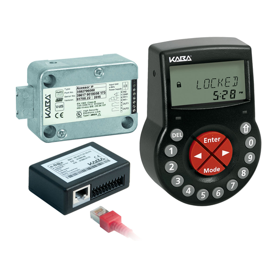
dormakaba Quick reference guide
External connections to / from the Axessor safe lock
Terminals/
Description
Sockets
1 / 2
Output 2
Factory setting: lock
open (OR boolean
operation with bolt
open or motor open
or door open)
3 / 4
Output 1
Factory setting:
duress alarm
5(-) / 6(+)
Input 1
Factory setting: off
(not assigned)
7 / 8
Input 2
Factory setting: off
(not assigned)
X1 / X2
Connection for
input unit, eBox or
power supply
Note
All Axessor safe lock inputs and outputs are configurable with the
AS284-USBW or AS284-NETW Axessor Programming Software.
Safe locks: Axessor series
Unit
Remarks
Resistive Load:
Relay with potential-free
working contact, Normally
30VDC / 2A
Open (NO). Contact is open,
50VAC / 0.5A
when lock is closed.
Resistive Load:
Relay with potential-free
working contact, NO. Contact
30VDC / 2A
is closed, when duress alarm is
50VAC / 0.5A
active.
12VDC /
---
min. 13mA,
max. 20mA
Potential-free
Use a micro switch with gold-
contact only
plated contact 12VDC/50mA
(do not apply
(e.g. DB series by Cherry).
any voltage !)
If Input 2 is assigned as "door
contact" and not inverted, an
open switch contact stands
for "door open". The bolt is
open as long as pins 7 and 8
remain electrically
disconnected.
---
Use the connecting cable in
the package. Only use the
original Axessor power supply.
2018-03
3