Canton InWall 700 Manual de instrucciones - Página 4
Navegue en línea o descargue pdf Manual de instrucciones para Altavoces Canton InWall 700. Canton InWall 700 8 páginas.
In der Regel geht eine Gefahr eher von zu leistungsschwachen
Verstärkern aus, da sie beim Versuch, durch Aufdrehen von Lautstär-
ke- und Klangreglern mehr Schalldruck zu erzielen, übersteuert
werden und durch sogenanntes "Clipping" Obertöne erzeugen, die
insbesondere die Hochtöner des Systems zerstören können.
Um eine Beschädigung der Lautsprecher-Chassis zu verhüten, sind
unsere InWall Lautsprecher mit einem Überlastschutz ausgestattet.
Bei drohender Überlastung wird – deutlich hörbar – der Pegel
abgesenkt. Drehen Sie in diesem Fall bitte den Lautstärkeregler Ihres
Verstärkers zurück. Nach erfolgter Abkühlung arbeiten die Lautspre-
cher wieder normal.
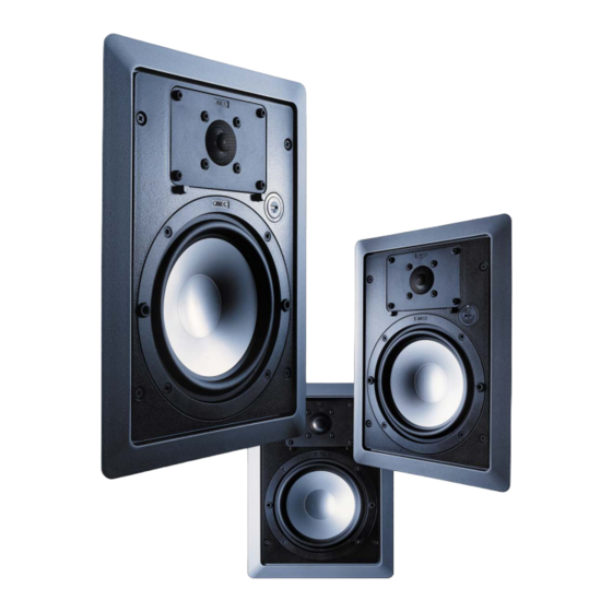
2 x InWall Lautsprecher Systeme
2 x Blende
2 x Gitter
2 x Dichtungen
1 x Einbau-Schablone
1 x Beipack
a) 8 x Schrauben M 4 x 20 DIN 965
b) 8 x Schrauben B 4,2 x 22 DIN 7982
c) 8 x Schrauben M 4 x 50 DIN 965
d) 12 x Zuschnitte "Gittersicherung"
e) 8 x Befestigungslasche
Packungsinhalt / Package Contents
a
Montage / Installation
As a rule, danger to loudspeakers is more likely to be caused by
low-powered amplifiers since, when attempting to achieve
greater sound pressure by turning up the volume and tone
controls, they are overdriven and go into so-called „clipping",
creating overtones which can destroy speaker tweeters in
particular.
To prevent damage to loudspeaker drivers, our InWall speakers
feature overload protection. In event of impending overload, the
level is audibly lowered. In this case, please turn down the volume
control on your amplifier. After cooling off, the speakers will again
perform normally.
c
b
d
e
Benutzen Sie die beigefügte Einbauschablone, um die
genaue Größe des Wandausschnittes festzulegen. Der
Außenrand der Schablone gibt die Größe der Blende an.
Der mit Pfeilen gekennzeichnete Innenrand gibt die Größe
der Einbauöffnung vor. Die Abmessungen des Ausschnittes
betragen 200 mm x 279,5 mm.
Use the enclosed installation template to ascertain the
exact size of the wall cutout. The outer edge of the
template indicates the size of the cover trim. The inner
edge, identified by arrows, indicates the size of the
installation opening. Dimensions of the cutout are 200
mm x 279.5 mm.
Schaffen Sie nun eine entsprechende Einbauöffnung in
Ihrer Wand bzw. Decke. Beim Verlegen der Lautsprecher-
kabel vom Verstärker zum Einbauort ist zu beachten, dass
die Kabelenden etwa 30 cm über den Wandausschnitt
hinausragen. Dies erleichtert Ihnen später die Befestigung
an den Lautsprecherklemmen der InWall Systeme.
Now hollow out an appropriate installation opening in the
wall/ceiling. When laying loudspeaker cable from
amplifier to installation point, be sure that the cable ends
protrude about 30 cm beyond the wall cutout. This later
simplifies fastening to the InWall systems' speaker clamps.
2 x InWall Loudspeaker Systems
2 x Installation Frames
2 x Grilles
2 x Sealing Strips
1 x Installation Template
1 x Hardware Pack
a) 8 x Screws M 4 x 20 DIN 965
b) 8 x Screws B 4.2 x 22 DIN 7982
c) 8 x Screws M 4 x 50 DIN 965
d) 12 x „Felt Stickers"
e) 8 x Mounting Tabs