Baumer HUBNER BERLIN HOG 10 Instrucciones de montaje y funcionamiento - Página 8

Navegue en línea o descargue pdf Instrucciones de montaje y funcionamiento para Media Converter Baumer HUBNER BERLIN HOG 10. Baumer HUBNER BERLIN HOG 10 40 páginas. Incremental encoder with connecting cable ölfle
También para Baumer HUBNER BERLIN HOG 10: Manual de instrucciones de instalación y funcionamiento (36 páginas), Manual de instrucciones de instalación y funcionamiento (40 páginas), Manual de instrucciones de instalación y funcionamiento (40 páginas), Instrucciones de montaje y funcionamiento (40 páginas), Instrucciones de montaje y funcionamiento (40 páginas), Instrucciones de montaje y funcionamiento (32 páginas), Instrucciones de montaje y funcionamiento (36 páginas), Instrucciones de montaje y funcionamiento (36 páginas), Instrucciones de montaje y funcionamiento (28 páginas)
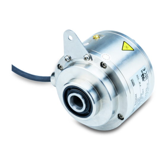
Baumer HUBNER BERLIN HOG 10 Instrucciones de montaje y funcionamiento
3
Vorbereitung / Preparation
3

Vorbereitung

3.1
Lieferumfang Gerät
6
7
8
5
4
11
Gehäuse HOG 10
1
Gehäuse FSL
2
Einseitig offene Hohlwelle oder Konuswelle
3
mit Schlüsselfläche SW 13 mm
Spannelement (nur bei einseitig offener Hohlwelle)
4
Stützblech für Drehmomentstütze
5
Sechskantschraube M6x18 mm,
6
ISO 4017, SW 10 mm
Scheibe B6, ISO 7090
7
Selbstsichernde Mutter M6,
8
ISO 10511, SW 10 mm
Rotor FSL
9
Torxschraube M4x12 mm
10
Erdungsband ~230 mm lang
11
Klemmenkasten HOG 10
12
Klemmenkasten FSL
13
Option EMS: Status LED
14
siehe Abschnitt 6.1.5.
Option Heizung, siehe Abschnitt 6.1.6.
15
Option M: Redundante Abtastung
1)
Option EMS:
HOG
10.2
+ FSL
2)
Option M + EMS:
HOG
10.2 M
3)
5
1)
2)
2) 3)
12
14
14
1
15
,
2) 3)
HOG 10.2
M
+ FSL
+ FSL
3

Preparation

3.1

Scope of delivery of the device

2
13
12
Housing HOG 10
1
Housing FSL
2
Blind hollow shaft or cone shaft
3
with spanner flat 13 mm a/f
Clamping element (only for blind hollow shaft)
4
Support plate for torque arm
5
Hexagon screw M6x18 mm,
6
ISO 4017, 10 mm a/f
Washer B6, ISO 7090
7
Self-locking nut M6,
8
ISO 10511, 10 mm a/f
Rotor FSL
9
Torx screw M4x12 mm
10
Earthing strap, length ~230 mm
11
Terminal box HOG 10
12
Terminal box FSL
13
Option EMS: Status LED
14
see section 6.1.5.
Option heating, see section 6.1.6.
15
Option M: Redundant sensing
1)
Option EMS:
HOG
2)
Option M + EMS:
3)
Baumer_HOG10-FSL-T2_II_DE-EN (17A2)
9
3
,
2) 3)
HOG 10.2
M
+ FSL
10.2
+ FSL
HOG
10.2 M
+ FSL
MB071.1T2 - 11069399
10
2