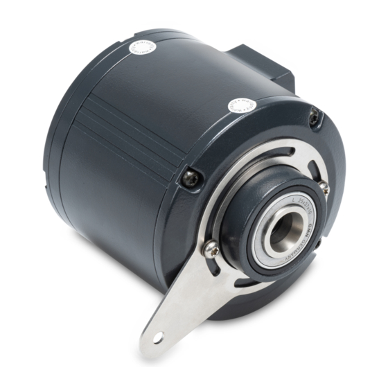
Baumer HUBNER BERLIN PROFI NET microGen HMG10P Manual de instrucciones - Página 2
Navegue en línea o descargue pdf Manual de instrucciones para Media Converter Baumer HUBNER BERLIN PROFI NET microGen HMG10P. Baumer HUBNER BERLIN PROFI NET microGen HMG10P 44 páginas. Incremental encoder with magnetic sensing
También para Baumer HUBNER BERLIN PROFI NET microGen HMG10P: Instrucciones de montaje y funcionamiento (32 páginas), Instrucciones de montaje y funcionamiento (40 páginas)

List of contents
List of contents
1 About this document...................................................................................................................................
1.1
Purpose ..............................................................................................................................................
1.2
Warnings in this manual .....................................................................................................................
1.3
Labels in this manual ..........................................................................................................................
1.4
Disclaimer ...........................................................................................................................................
1.5
Scope of delivery ................................................................................................................................
1.6
Name plate .........................................................................................................................................
1.7
Maintenance and service life ..............................................................................................................
1.8
Approvals and warranty ......................................................................................................................
1.9
Temperature range for operation and storage....................................................................................
2 General information ....................................................................................................................................
3 Transport and storage ................................................................................................................................
3.1
Transport ............................................................................................................................................
3.2
Delivery inspection..............................................................................................................................
3.3
Storage ...............................................................................................................................................
4 Description...................................................................................................................................................
4.1
Rotary encoder ...................................................................................................................................
4.2
Mounting accessories (not included) .................................................................................................. 10
4.3
Tools required..................................................................................................................................... 11
5 Installation.................................................................................................................................................... 12
5.1
Positioning the support plate .............................................................................................................. 12
5.2
Attaching the torque arm to the device ............................................................................................... 14
5.3
Blind hollow shaft encoder installation................................................................................................ 15
5.4
Mounting the encoder to cone shaft ................................................................................................... 17
5.5
Hollow shaft mount ............................................................................................................................. 19
5.6
Mounting the torque arm at drive........................................................................................................ 21
5.6.1
HMG10 installation versus HOG10 ....................................................................................... 22
5.7
Avoiding and calculating angular errors.............................................................................................. 24
6 Electrical installation................................................................................................................................... 25
6.1
EtherNet/IP ......................................................................................................................................... 25
6.1.1
Features EtherNet/IP ............................................................................................................ 25
6.1.2
Pin assignment EtherNet/IP .................................................................................................. 26
6.1.2.1
6.1.2.2
6.1.3
View in bus junction box ....................................................................................................... 27
6.1.4
Set IP address ...................................................................................................................... 27
6.2
Terminal box ....................................................................................................................................... 28
6.2.1
Pin assignment at terminal box ............................................................................................. 28
6.2.2
Output signals additional incremental output (optional) ........................................................ 28
ii
Mating connector (4-pin, A-coded) ................................................................... 26
Mating connector (4-contact D-coded) ............................................................. 27
Operating Manual
HMG10 & HMG10P EtherNet/IP | V1, T1
Baumer Hübner
4
4
4
4
4
5
5
6
6
6
7
8
8
8
8
9
9
