Baumer PMG10P Instrucciones de montaje y funcionamiento - Página 24

Navegue en línea o descargue pdf Instrucciones de montaje y funcionamiento para Media Converter Baumer PMG10P. Baumer PMG10P 36 páginas. Absolute encoder
También para Baumer PMG10P: Instrucciones de montaje y funcionamiento (32 páginas), Instrucciones de montaje y funcionamiento (32 páginas), Manual de instrucciones (44 páginas), Manual de instrucciones (44 páginas), Manual de instrucciones (40 páginas), Manual de instrucciones (40 páginas), Manual de instrucciones (40 páginas), Manual de instrucciones (36 páginas)
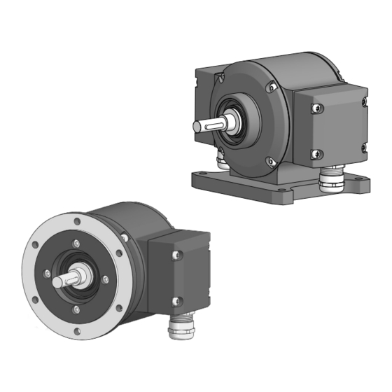
Baumer PMG10P Instrucciones de montaje y funcionamiento
ELECTRICAL CONNECTION / ELECTRICAL CONNECTION WITH RADIAL FLANGE CONNECTORS
5.8.2

Assignment flange connectors

)
Do not connect voltage supply to outputs! Danger of damage!
Please, beware of possible voltage drop in long cable leads (inputs and out-
puts)!
5.8.2.1
First flange connector [C]
SSI
Programming interface (only PMG10P)
Additional output incremental 1 (option)
Flange connector M23 (male, 17-pin, clockwise)
5.8.2.2
Second flange connector [D]
Additional output incremental 2 (option)
Speed switch (option)
)
Flange connector M23 (male, 12-pin, clockwise)
Additional output incremental (option)
1)
Speed switch (option)
2)
Programming interface (only PMG10P)
3)
21/29
PIN
1
8
1
9
2
10
12
2
7
3
6
3
11
4
5
4
5
6
7
8
9
The TTL/HTL output at the additional output incremental 2 is electrically
isolated and requires a separate power supply�
8
9
1
12
10
2
7
3
6
11
4
5
ASSIGNMENT
nE−
DIR
dnu / SB
3)
nE+
PRE
dnu / SA
3)
Ub
C+
C−
PIN
ASSIGNMENT
1
dnu / B−
1)
2
nE−
3
dnu / R+
1)
4
dnu / R−
1)
5
dnu / A+
1)
6
dnu / A−
1)
MB245EN - 11171693, 19A3, Baumer_PMG10-SSI_II_EN
PIN
ASSIGNMENT
10
0V
11
Internal shield
12
dnu / B+
1)
13 dnu / B−
1)
14
D+
15
dnu / A+
1)
16 dnu / A−
1)
17 D−
PIN
ASSIGNMENT
7
dnu / SP+
2)
8
dnu / B+
1)
9
dnu / SP−
2)
10
0V
1)
11
nE+
12
Ub
1)