Baumer CombiLyz AFI4 Manual - Página 6
Navegue en línea o descargue pdf Manual para Instrumentos de medida Baumer CombiLyz AFI4. Baumer CombiLyz AFI4 7 páginas. Conductivity transmitter
También para Baumer CombiLyz AFI4: Instrucciones de uso (36 páginas)
Electrical connection
Left side electrical connection (Front view)
1
1- 15...35 vdc (+)
2- Cond. (-)
2
Left side M12, 4 pin connector
1. Brown
Supply (+)
2. White
Cond. (-)
3. Blue
Supply (-)
4. Black
Cond. (+)
Note :
If a M12 4-pin connector for left and right side is selected the AFI4 is di-
rectly compatible with the previous Baumer ISL conductivity transmitter.
To connect the FlexProgrammer to the transmitter
Com 1
Red clip
Com 2
Black clip
The data entered to the transmitter will automatically be displayed on
the DFON display via the ribbon cable (UnitCom)
To connect the FlexProgrammer to the DFON display
Com 1
Red clip
Com 2
Black clip
Colour change, relay set-points and error messages etc. can be
setup be set in the DFON display.
To set the external input for range selection
Range
S1
S2
1
N.C.
N.C.
2
24 VDC
N.C.
Electrical connection on the AFIx transmitter
Display (Unit Com)
Supply +
Supply -
S1
S2
Com 1
Ground
Note:
The ground connection (
) is to be connected with the cable shield if
using cable gland and shielded cable.
www.baumer.com
4
Cond. (+) -4
15...35 vdc (-) -3
3
(15...35 vdc)
(4...20 mA)
(15...35 vdc)
(4...20 mA)
Range
S1
S2
3
N.C.
24 VDC
4
24 VDC
24 VDC
+ Temp
- Temp
+ Cond
- Cond
Com 2
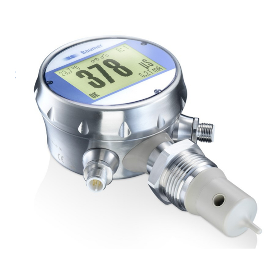
CombiLyz AFI4 / AFI5
Inductive conductivity transmitter
Right side electrical connection (Front view)
1
1- S1
2- °C (-)
2
Right side M12, 4-pin connector
1. Brown
S1
2. White
Temp. (-)
3. Blue
S2
4. Black
Temp. (+)
Note :
The pin 2 in left connection and pin 2 in right connection can be con-
nected as common - for both Con. and Temp. 4...20 mA output.
Right side electrical connection with relay output
Relay 1 - 5
Relay 1 - 6
Temp. (-) (4...20 mA) - 7
S1 (external input) - 1
Right side M12, 8 pin connector
1. White
S1
2. Brown
Temp. (+)
3. Green
Relay 2
4. Yellow
Relay 2
5. Grey
Relay 1
6. Light red
Relay 1
7. Blue
Temp. (-)
8. Red
S2
Note:
The pin 2 in left connection and pin 7 in right connection can be con-
nected as common - for both Con. and Temp. 4...20 mA output.
Electrical connection on the display with relay output
1. Not connected
2. Not connected
3. Green
Relay 2
4. Yellow
Relay 2
5. Grey
Relay 1
6. Light red
Relay 1
(3 + 5 can be connected
common)
UnitCom
Ribbon cable
to transmitter
To connect the
Flexprogrammer
Com 1
Red clip
Com 2
Black clip
Data sheet AFI4 / AFI5
4
°C (+) -4
S2 -3
3
(external input)
(4...20 mA)
(external input)
(4...20 mA)
4 - Relay 2
5
6
4
8
3
7
3 - Relay 2
2
1
2 - Temp. (+) (4...20 mA)
8 - S2 (external input)
(external input)
(4...20 mA)
(4.. .20 mA)
(external input)
N.C. N.C.
Relay 2
Com 1
UnitCom
Relay 1
Com 2
Page 6 / 7