Baumer HUBNER TDPZ 0,2 Series Instrucciones de montaje y funcionamiento - Página 31

Navegue en línea o descargue pdf Instrucciones de montaje y funcionamiento para Generador portátil Baumer HUBNER TDPZ 0,2 Series. Baumer HUBNER TDPZ 0,2 Series 32 páginas. Tachogenerator (doppel-tachogenerator), tachogenerator (twin tachogenerator)
También para Baumer HUBNER TDPZ 0,2 Series: Manual de instrucciones de instalación y funcionamiento (32 páginas), Manual de instrucciones de instalación y funcionamiento (28 páginas), Instrucciones de montaje y funcionamiento (28 páginas), Instrucciones de montaje y funcionamiento (32 páginas), Instrucciones de montaje y funcionamiento (32 páginas), Instrucciones de montaje y funcionamiento (28 páginas)
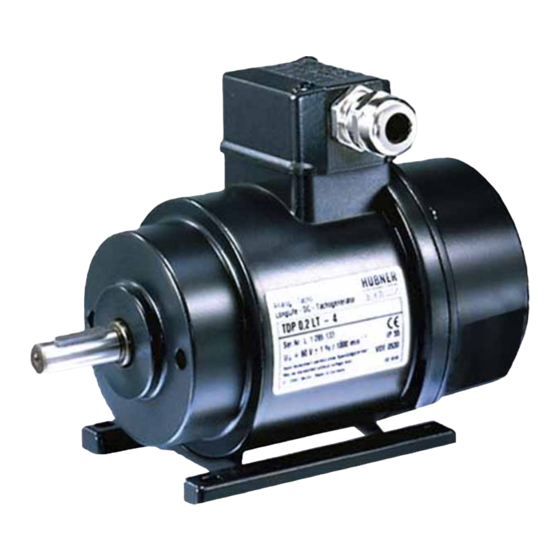
Baumer HUBNER TDPZ 0,2 Series Instrucciones de montaje y funcionamiento
• Operating temperature:
• Resistance:
• Connection:
TDP 0,2 + ESL 90, TDP 0,2 + ESL 93
• Rotor moment of inertia:
• Weight approx.:
TDPZ 0,2 + ESL 90, TDPZ 0,2 + ESL 93
• Rotor moment of inertia:
• Weight approx.:
10.4

Type data

voltage
Type
[mV/rpm]
TDP0,2LT(LS)-6
TDP0,2LT(LS)-7
TDP0,2LT(LS)-10
TDP0,2LT(LS)-5
TDP0,2LT(LS)-4
TDP0,2LT(LS)-3
TDP0,2LT(LS)-1
TDPZ0,2LT-7
TDPZ0,2LT-10
TDPZ0,2LT-5
TDPZ0,2LT-4
TDPZ0,2LT-3
Superimposed ripple (for τ
10.5

Replacement switching diagram

Polarity for positive direction of rotation, see section 5:
TDP:
TDP:
1A1/2A1: +
R
L
A
A
U
(n)
0
Tachogenerator
τ
≈ R · C
τ
RC
A
MB079.2 - 11115290
Open-
Minimum load required
circuit
depending on speed range
(DC)
0 - 3000:
U
R
0
L
[kΩ]
10
≥0.1
20
≥0.3
30
≥0.7
40
≥1.2
60
≥2.7
100
≥7.5
150
≥16
Twin tachogenerator with two separate tachogenerator voltages
(The data refer to each of the two tachogenerator outputs)
20
≥1.2
30
≥2.7
40
≥4.8
60
≥11
100
≥30
= 0.7 ms):
≤0.5% peak-peak
RC
A1: +
A2: -
1A2/2A2: -
R
A1
U(n)
R
L
A2
L
A
R
L
Baumer_TDP02-ESL-TDPZ02-ESL_II_DE-EN (20A1)
-20...+85 °C
IEC 60068-2-6:2007: Vibration 5 g, 10-2000 Hz
IEC 60068-2-27:2008: Shock 150 g, 1 ms
2x terminal box
1.4 kgcm
2
3.2 kg
1.5 kgcm
2
3.4 kg
[rpm]
0 - 6000:
0 - n
R
R
L
L
[kΩ]
[kΩ]
≥0.3
≥0.9
≥1.2
≥3.3
≥2.7
≥7.5
≥5
≥13.5
≥11
≥30
≥30
≥30
---
≥30
≥4.8
≥14
≥11
≥30
≥20
≥54
≥44
≥120
≥120
---
≤0.2% rms
(VDE)
(VDE)
C
U(n) = U
(n)
0
Maximum
Armature
operating
resistance
speed
:
max
n
R
max
A
[rpm]
10000
10000
10000
10000
10000
6000
4000
10000
10000
10000
10000
6000
U(n)
-n
-U(n)
R
L
≈ U
(n) for R > R
R
+ R
0
A
L
10
Armature
inductance
(20 °C)
L
A
[Ω]
[mH]
3
6
11
23
26
50
47
90
99
200
271
550
630
1260
19
45
42
103
70
170
160
390
445
1080
U
(n) ≈ U(n)
0
n
>> R
L
A
28