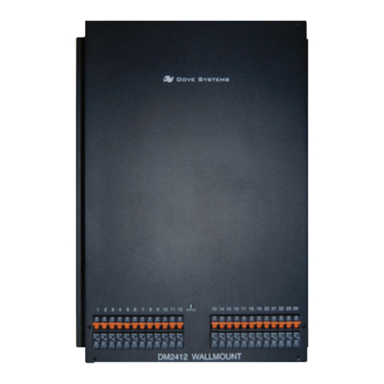
Dove DM-2412 Manual del usuario - Página 4
Navegue en línea o descargue pdf Manual del usuario para Regulador de intensidad Dove DM-2412. Dove DM-2412 6 páginas. Digital dimmer

OWNER'S MANUAL
F// Channel Selection and Testing
The thumbwheel switch inside the pack is the channel selection switch.
The number shown is the starting dimmer. Valid starting dimmer
numbers range from 1 to 489. The starting dimmer number determines
the setting for the entire pack of twenty-four dimmers. If, for example,
the starting dimmer number is 25, the pack reads control signals for
channels 25 through 48. When the first digit of the thumbwheel
switch reads "6", the pack is in load testing mode. The second and
third digits show the dimmer being tested, from 1 to 24. The load test
forces the output of the dimmer to full. This is helpful for focusing
and troubleshooting. (e.g. Which channel is that? Is the lamp burnt
out?) A setting of "600" drives all lamps at 20%.
G// Indicators
The status indicator LED is used to check the Dimmermaster for proper
control and power connections. The LED shines green when it is
receiving power and a valid DMX signal, and red when it is receiving
power but a bad signal. The LED shines red when it is receiving an
analog signal only. No light at all means that it is not receiving power.
H// Internal Switches
A 9 position internal DIP switch sets various options. These include
DMX line termination and nondim operation. DIP switch functions are
printed on the circuit board. To terminate the DMX line (this is the
last dimmer in the DMX string), turn on DIP switch number 1 (which
terminates DMX pins 2 and 3) and 9 (which terminates
DMX pins 4 and 5). All outputs at or above a specified number may be
set to nondim. When set to nondim, an output is full when fed with
50% (DMX level 128, analog +5V). or higher. Below this threshold,
the output is off. The first nondim output is set using binary coding
on the DIP switch. For example, if outputs 7 and above are to be
nondim, switches 2, 3, and 4 would be set to the on position, since
these correspond to nondim 1, nondim 2, and nondim 4. 1+2+4=7,
so outputs 7 and above will be nondim.
DIP switch 7 Enables Idle-Current when On. This feature can extend the
life of incandescent bulbs but can prevent solid-state lights (LEDs)
from turning off.
DOVE LIGHTING SYSTEMS
805.541.8292\\805.541.8293
INC.\\3563 SUELDO STREET UNIT E
SAN LUIS OBISPO\\ CA 93401
OWNER'S MANUAL
:Control Connections
DMX Connector DB25M Analog
1
Common 1 Channel 1 Control (0 to 10V)
2
- Data 2 Channel 2 Control (0 to 10V)
3
+ Data 3 Channel 3 Control (0 to 10V)
4
Return Data opt 4 Channel 4 Control (0 to 10V)
5
Return Data opt 5 Channel 5 Control (0 to 10V)
6
Channel 6 Control (0 to 10V)
7
Channel 7 Control (0 to 10V)
8
Channel 8 Control (0 to 10V)
9
Channel 9 Control (0 to 10V)
10
Channel 10 Control (0 to 10V)
11
Channel 11 Control (0 to 10V)
12
Channel 12 Control (0 to 10V)
13
Channel 13 Control (0 to 10V)
14
Channel 14 Control (0 to 10V)
15
Channel 15 Control (0 to 10V)
16
Channel 16 Control (0 to 10V)
17
Channel 17 Control (0 to 10V)
18
Channel 18 Control (0 to 10V)
19
Channel 19 Control (0 to 10V)
20
Channel 20 Control (0 to 10V)
21
Channel 21 Control (0 to 10V)
22
Channel 22 Control (0 to 10V)
23
Channel 23 Control (0 to 10V)
24
Channel 24 Control (0 to 10V)
25
Common
When the temperature of the heatsink exceeds 75 degrees Celsius,
the control is cut off. This prevents overheating. When the heatsink
cools, the loads begin to work again. If this happens, the air
circulation around the dimmer should be improved. Check that the
internal fan has not failed.
DOVE LIGHTING SYSTEMS
805.541.8292\\805.541.8293
INC.\\3563 SUELDO STREET UNIT E
SAN LUIS OBISPO\\ CA 93401
