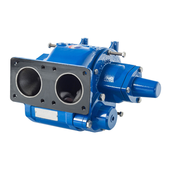
Dover PSG Mouvex CC10-24 Instalación Funcionamiento y mantenimiento - Página 12
Navegue en línea o descargue pdf Instalación Funcionamiento y mantenimiento para Bomba de agua Dover PSG Mouvex CC10-24. Dover PSG Mouvex CC10-24 18 páginas.

8. DISMANTLING REASSEMBLY (continued)
When the endplate is free on the shaft, hold it by hand sup
porting it.
Once the endplate is out, the rotating part 697 of the mecha
nical seal stays in place on the shaft. Caution not to scratch
friction face.
8.2 Dismantling on drive side
Uncouple the pump by removing the coupling.
Remove the key 508 and clean the end shaft. Then proceed
in the same way as when dismountling on the other side. It is
necessary to push cover 705 slightly a side to avoid damaging
Oring 707 on key.
Unscrew the screws 723A, remove the cover 705 with its seal
714A taking care not damaging seal 707.
Remove the circlip 537.
Operate then in a identical way in § D
.
TO DRIVE SYSTEM
Open the pump on one side or the other.
Remove the vanes 317.
Check for wear (see § M
AINTENANCE
If vane wear is abnormal, check surface condition of body and of
endplate faces.
Refit the vanes (new if necessary) respecting the direction of
assembly and check that they slide freely.
Reassemble the pump and check that it rotates freely when turned
by hand.
NT 1010P00 09 20 CC1024 A e
ISMANTLING ON SIDE OPPOSITE
9. CHANGING THE VANES
).
8.3 Reassembly
When putting the endplate back into place, take care to
have the shaft seal drive lugs facing the notches on rotor.
Refit in the endplate the Nilos ring 733, the ball bearings 703
and the spacer 734. Then replace the cover 712 or 705 on the
front cover 401 with screws 723.
Lubricate the shaft 501 slightly.
Make sure that the endplate seal 403 is correctly positioned,
check it and change it if necessary.
Make sure the stationary seal face 604 of the mechanical seal
and its seal 605 are in the front cover 401 and the rotating
part 697 is on the shaft. Then, position the front cover 401 on
the shaft and approach it as far as possible by hand.
Finish fitting the endplate, screwing the 2 nuts 412 gradually
on to the 2 screws 411.
Make sure that endplate is centred while screwing.
When the endplate is in place, remove the screws 411 and
their nuts 412 and screw them up taking care to position one
of the drainage port L pointing down.
Replace the screws 410.
Remove the cover 712 or 705.
Replace the circlip 537.
Replace the cover 705 or 712 with its seal 707 after check
condition of seal.
Free the shaft line by a light blow of mallet on its extremity and
make sure that the pump rotates freely when turned by hand.
8.4 Assembly of flange for hydraulic trunk
Refer to Instructions NT 1010K00 A
HYDRAULIC TRUNK ON PUMP
12/18
SSEMBLY OF FLANGE FOR
CC8 CC10.
