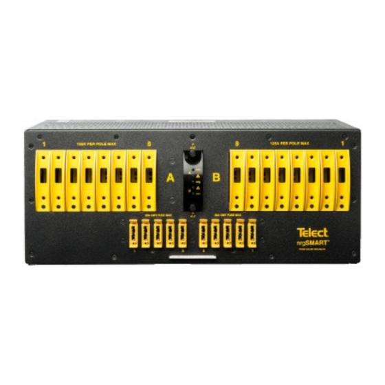
Amphenol Telect nrg600BT08-M Manual de instalación - Página 8
Navegue en línea o descargue pdf Manual de instalación para Disyuntores Amphenol Telect nrg600BT08-M. Amphenol Telect nrg600BT08-M 20 páginas. 600a load center with nrgsmart remote monitoring

Power A
Fuse Alarm A
LED State
PWR A/B
Green
Operating normally
Blinking green
PWR B, boot loader loading
Yellow
PWR A, boot loader mode
RED
PWR A or PWR B feed
voltage alarm < -20VDC
RED single blink
N/A
RED double blink
N/A
No light
No power to feed
Boot Loader Mode
The nrg600BT08-M alarm card will receive remote firmware updates automatically from the nrgCONTROL-BT. The boot loader mode is indicated by a
yellow PWR A LED. In this mode, the power and fuse LEDs are used for diagnostics and do not represent the power and fuse status. A blinking green
PWR B LED in conjunction with the yellow PWR A LED indicates the firmware is actively being updated. The update process lasts approximately
7 seconds.
NOTE: The following steps require that the nrg600BT08-M is connected to an nrgCONTROL-BT controller. The nrgCONTROL-BT provides power to
the nrg600BT08-M's alarm card, which is required for steps 17-19 and steps 22-27. Reference the nrgNET connectivity section for further details.
17.
Enable protection device (fuse or breaker) at primary PDU to turn on Feed A to Side A of panel and then check voltage and polarity at input
connectors of panel. Also, check:
•
PWR A LED on front of panel turns on (green).
•
PWR B LED is off
18.
With PWR A LED green (normal operation) — but with PWR B LED off — test power-fail relay and contacts at PWR alarm terminals on rear
of panel:
Expect open circuit (∞Ω) between Terminals C and NC.
•
Expect an continuity (0Ω) between Terminals C and NO.
•
19.
Also, test fuse alarm relay contacts at fuse (CB/Fuse Alarm) terminals on the rear of the panel:
•
Expect continuity (0Ω) between Terminals C and NC.
•
Expect an open circuit (∞Ω) between Terminals C and NO.
20.
Repeat Steps 17 through 19 to power up Side B. PWR A and PWR B LEDs must both be green.
nrg600BT08-M
Figure 3: nrg600BT08-M Alarm Card
FUSE Alarm A/B
Operating normally
N/A
N/A
A feed or B feed fuse alarm
N/A
N/A
No alarm
8
nrgNET Connection to the
nrgCONTROL-BT
Fuse Alarm B
Power B
nrgNET Connection
Active communication to nrgCONTROL-BT
Used for visual identification through controller command
N/A
Connected to nrgCONTROL, but no communication to this
specific panel within last 3 seconds
Defective panel. Contact Amphenol Network Solutions for
replacement.
Invalid communication to nrgCONTROL. Check that
COM+ and COM- did not get swapped.
No power present on nrgNET IN connector
Amphenol Network Solutions
All rights reserved. 12.05.19 145121-2 A0
509.926.6000 – amphenol-ns.com
