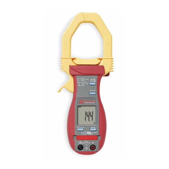
Amprobe ACDC-100 TRMS Manual del usuario - Página 8
Navegue en línea o descargue pdf Manual del usuario para Multímetro Amprobe ACDC-100 TRMS. Amprobe ACDC-100 TRMS 16 páginas. Versatile ac/dc clamp-on multimeter series

HoLD
press the HoLD button momentarily toggles to hold mode for all of the functions. To release
the HoLD feature momentarily press the HoLD button.
MAX
press the HoLD button for 1 second or more activates the MAX holD feature for the VDC,
VAC and ACA functions. To release the MAX holD feature press the HoLD button for 1
second or more.
r Relative Zero mode
Relative Zero mode allows the user to offset the subsequent meter measurements with
the displayed reading as the reference value. The display will now show readings relative
to the stored reference value. That is, display = reading - stored value. pressing the button
momentarily toggles to relative mode.
SELECT / backlight ( �)
press Backlight button more than 1 second, enable/disable Backlight.
press the SeleCT / Backlight button to step through the manually selected A� and Ω
functions.
A� → A� and Ω → � → � → �
Manual or Auto-ranging
press the RAnge button momentarily to select manual-ranging mode. The lCD symbol
turns off. press the button momentarily again to step through the Ranges. press and hold the
RAnge button for more than 1 second to resume auto-ranging.
Auto Power off function
The clamp meter powers down automatically after approximately 30 minutes of inactivity.
To turn it back on, move the function selector switch to off and back to a measuring
function.
To disable Auto power off, press and hold the holD button while moving the slide switch to
the desired function from off.
oPERATIoN
DC Voltage (see fig. 1)
1.
Set the function Switch to
2.
Connect the test leads: Red to
3.
Connect the test probes to the circuit test points.
4.
Read the display, and if necessary, correct any overload (
AC Voltage (see fig. 1)
1.
Set the function Switch to
2.
Connect the test leads: Red to
3.
Connect the test probes to the circuit test points.
4.
Read the display, and if necessary, correct any overload (
V�.
+, Black to CoM.
V�.
+, Black to CoM.
7
0L) conditions.
0L) conditions.
