DPS Telecom Building Status Unit II Manual del usuario - Página 7
Navegue en línea o descargue pdf Manual del usuario para Sistema de seguridad DPS Telecom Building Status Unit II. DPS Telecom Building Status Unit II 20 páginas.
4
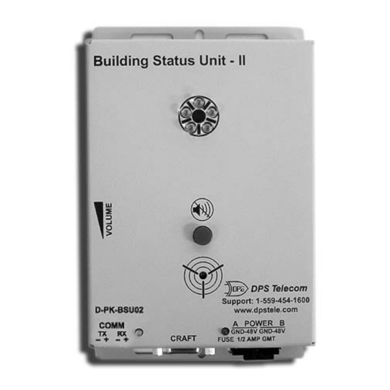
Specifications
Dimensions:
Mounting:
Power Input:
Current Draw:
Interfaces:
Visual Interface:
Audible Interface:
Operating Temperature:
Operating Humidity:
5
Tools Needed
To install the Building Status Unit II, you'll need the following:
A small screw driver
6
Install the BSU II
6.1
Hardware Mounting
Mount the BSU II in the desired location using the mounting screws provided. Position the case onto the screws
then slide it down to lock into place.
6.2
Wire for Communication
6.2.1
Connection to the NetGuardian 832A
The BSU II support is available for the NetGuardian. Contact DPS for BSU II support for KDA, IAM or T/Mon
NOC.
Use the following steps to connect the BSU II to the NetGuardian:
1. Remove the screw-lug barrier plugs from the bottom of the BSU II.
Note: requires small screwdriver to work with small connectors.
2. Connect communication wires from data port 8 located on the back of the NetGuardian — see Figure 6.1 and
Table 6.A.
3. Connect communication wires from data port 8 to the 4 position barrier plug — refer to Figure 6.1 and Table
6.A.
Note: NetGuardian version 3.0H and above is required to connect the BSU II — see Section 8 for additional
NetGuardian configuration. The NetGuardian must have port 8 built with RS485 hardware.
5 1/8"H x 5"W x 1 1/2"D
wall mount — mounting screws (included)
–48VDC (–40 to –70 VDC)
100 mA
RS485
5 High intensity diffused red LEDs
Alarm speaker (Piezo)
+32° to +140° F (0° to +60° C)
0% to 95% non-condensing
A medium size screw driver
3