AMS AS5601 Manual de instrucciones - Página 6
Navegue en línea o descargue pdf Manual de instrucciones para Unidad de control AMS AS5601. AMS AS5601 12 páginas. Usb interface & programming box
También para AMS AS5601: Manual del usuario (13 páginas), Manual (13 páginas)

AS5601-SO_RD_ST
Operation Manual
The magnet is already aligned to get AGC values in the middle of the AGC range.
Note: If the magnetic field seen by the AS5601 would be below 8mT, the output is disconnected
and permanent angle programming would not be possible. The AB quadrature interface is not
updated as long as the magnet is away.
2.4 Electrical Setup
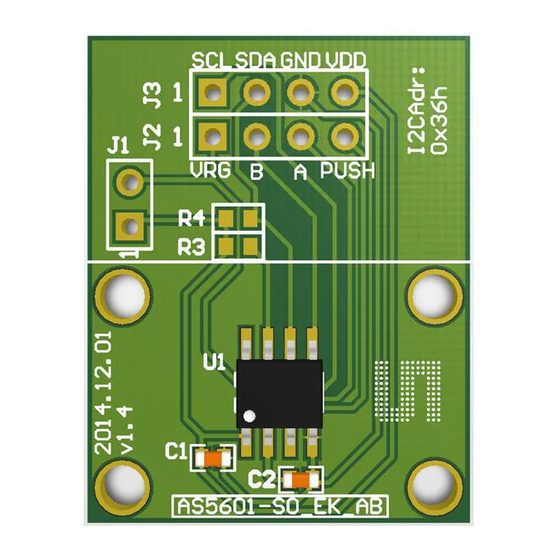
The reference module is many used in following configurations and can be supplied with 5V or in
3.3V mode. Use J1 to enable the 3.3V mode.
2.4.1 Incremental Mode
In this mode, the power supply and the pins A and B of the reference module are connected. Over
Programming interface the Zero position and the resolution can be configured for better
performance due to hardly any individual application.
Figure 4:
Using the board in incremental Mode
µC
2.4.2 Pushbutton Detection
In this mode, the power supply and the pin Push of the reference module are connected. Over the
programming interface the pushbutton detection can be adjusted.
Figure 5:
Using the board in push button mode
µC
www.ams.com
+
-
A
B
+
-
Push
Revision 1.0 / 30.06.2014
page 6/11
