DRAKE VM2551 Manual de instrucciones - Página 3
Navegue en línea o descargue pdf Manual de instrucciones para Modulador DRAKE VM2551. DRAKE VM2551 10 páginas. Commercial video modulator
También para DRAKE VM2551: Manual de instrucciones (12 páginas)

TABLE OF CONTENTS
2
3
Table of Contents / General Descrption
4
5
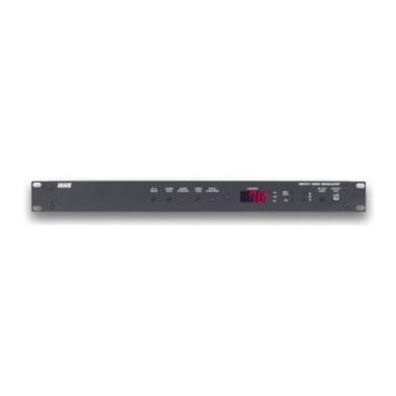
GENERAL DESCRIPTION
The Drake VM2551 Video Modulator is a vestigial
sideband unit with synthesized visual and audio carriers.
The VM2551 is designed to accept video and audio
baseband signals from a satellite receiver, video server,
VCR, camera, or similar equipment. Front panel video
and audio level controls and overmodulation indicators
permit setting the proper modulation levels. Synthesized
operation provides complete frequency agility, allowing
front panel selection of any standard, HRC, or IRC, CATV
channel from 2 to 78 and channels 95-99 or OFF AIR TV
channels 2-27. FCC required channel frequency offsets,
for aeronautical channels of zero, +12.5 kHz, or +25 kHz
are selected automatically and offset positive when
offsets are required.
Table of Contents / General Description
A / V
AUDIO
AUDIO
VIDEO
RATIO
LEVEL
OVER DEV
LEVEL
6
7
8
9
VIDEO
CHANNEL
OVER MOD
STD
HRC
IRC
The modulator accepts standard (sync negative) polarity
video at a 0.7 -1.5 Vpp level. A high quality IF SAW filter
eliminates adjacent channel interference.
IF loop-through capability in the VM2551 supplies an IF
output prior to channel conversion. This feature provides
the capability to replace the standard internally generated
IF output with an alternate source of composite IF, or
allows insertion of IF scrambling equipment.
The internally generated aural carrier may be disabled by
moving an internal jumper and an external 4.5 MHz
carrier can can be inserted via the rear panel 4.5 MHz
input.
These features, combined with a carefully designed low
intermodulation output stage, provide reliable operation
in a densely crowded SMATV or cable environment.
3
RF OUT
OUTPUT
LEVEL
TEST
ANT /
CATV
CH
SEL
