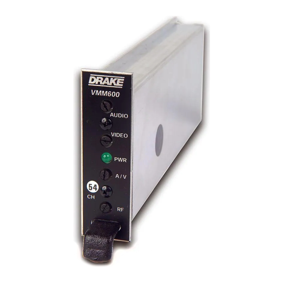
DRAKE VMM 860 Manual - Página 2
Navegue en línea o descargue pdf Manual para Modulador DRAKE VMM 860. DRAKE VMM 860 2 páginas. Video modulator system
También para DRAKE VMM 860: Manual de instrucciones (2 páginas), Manual de inicio rápido (2 páginas)

SPECIFICATIONS
SPECIFICATIONS
RF
Frequency Range:
VMM600-
54-600 MHz.
Factory set to one of the following
channels:
Cable Channels 1-86, 95-99 or
UHF-TV Channels 14-35.
VMM860-
600-864 MHz.
Factory set to one of the following
channels:
Cable Channels 87-135 or
UHF-TV Channels 36-69.
Output Level:
+45 dBmV, minimum.
Adjustable over a 12 dB range.
Output Impedance:
75 Ohms, return loss of 12 dB.
A/V Ratio:
Audio Carrier -10 to -22 dB
referenced to video carrier,
adjustable.
Frequency Stability:
+ 5 kHz (Visual Carrier).
Intercarrier Frequency:
4.5 MHz, ±50 Hz.
FCC Frequency Offsets:
All aeronautical channels are offset
positive.
Spurious Outputs:
-65 dBc, measured at -15 dB A/V
54 to 1000 MHz
ratio and with modulator output
level of +45 dBmV.
Broadband Noise:
-95 dBc, referenced to video
carrier.
(4 MHz BW and +36 MHz offset).
VIDEO
Input level for 87.5%
modulation:
1 Vp-p +3 dB, manual gain adjust
with front panel control.
Input Impedance:
75 Ohms, return loss of 18 dB
minimum.
Frequency Response:
20 Hz to 4.2 MHz, +1 dB.
Video S/N:
65 dB minimum, luminance
weighted.
Order From:
VIDEO (continued)
Differential Gain:
+3% (10 to 90% APL).
Differential Phase:
+3 degrees (10 to 90% APL).
C/L Delay:
Within 50 nSec. of 0 nSec.
(standard), or
FCC predistortion, (option).
AUDIO
Input Level for 25 kHz
Peak Deviation:
100 mV to 2.5 Vrms;
manual gain adjustment
with front panel control.
Input Impedance:
10 K Ohms, unbalanced.
Pre-Emphasis:
75 µS. (Defeatable via
jumper setting for BTSC
baseband stereo
compatibility).
Frequency Response:
40 Hz to 15 kHz, +1.0 dB
referenced to 75 µS
pre-emphasis curve.
(40 Hz-100 kHz ±0.5 dB if
pre-emphasis is defeated).
4.5 MHz Intercarrier Stability:
+50 Hz, frequency
synthesized.
Total Harmonic Distortion:
0.5% Maximum.
Hum and Noise:
-65 dB minimum, referenced
to 25 kHz peak deviation.
GENERAL
DC Power Input:
+12 VDC @ 150 to 220 mA,
channel dependent.
Operating Temperature:
+5 VDC @ 75 to 100 mA,
channel dependant.
Size:
0°C to +50°C.
Weight:
1"W x 3.5" H x 7.5"D.
11 oz.
Specifications subject to change without notice or obligation.
800-423-2594
www.multicominc.com
INSTALLATION
CONNECTIONS AND CONTROLS
All connections to and from each modulator
are made through the rear panel. Figure 3
illustrates an installation with 12 modulator units
combined through a passive signal combiner.
Additional channels can be added by using
additional VMM 600 or VMM 860 modulators
and
either
multi-por t
combiners
combinations of two-port combiners.
INSTALLATION NOTES
Level
adjustment
provides
optimum
performance in multi-channel installations. The
modulator outputs should be checked
periodically with a spectrum analyzer to
maintain a ± 1 dB variation of adjacent
channel carriers.
AUDIO INPUTS
AC POWER
CORD
VIDEO INPUTS
DC POWER
CABLE
RF COMBINER
R.L. DRAKE COMPANY
230 INDUSTRIAL DRIVE
FRANKLIN, OHIO 45005 U.S.A.
Aural/Visual (A/V) ratios should be held to
-15 dB or less. The output 'RF' and 'A/V
(Ratio)' controls are used respectively to make
these adjustments.
RACK MOUNTING
or
Adequate ventilation is very important in
multi-channel installations. Units should be
spaced apart by at least one panel height
wherever possible, and some air movement is
advisable in enclosed rack cabinets.
Excessive heat will shorten component life and
modulator performance will be degraded
without proper cooling.
VMM 600's/VMM 860's
SYSTEM OUT
Figure 3
®
