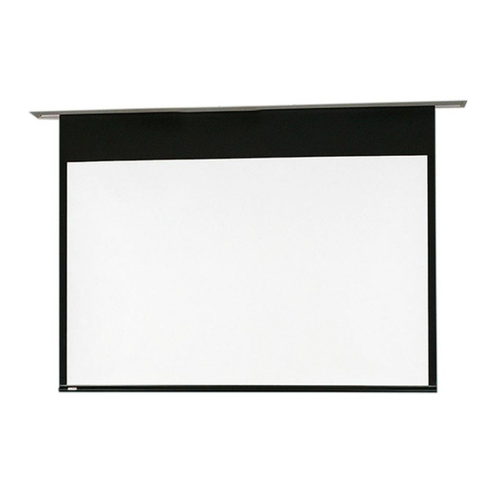
Draper Access FIT V Instrucciones de instalación y funcionamiento
Navegue en línea o descargue pdf Instrucciones de instalación y funcionamiento para Pantalla de proyección Draper Access FIT V. Draper Access FIT V 8 páginas. Electric projection screen
También para Draper Access FIT V: Instrucciones de instalación y funcionamiento (8 páginas)

Access FIT E and V 220V
Electric projection screen
Overview - Access Fit E and V Components
Hoisting Bracket
Mounting Bracket
Electrical
Cutout
Tab Tensioning
"V" Dowel
Shipping Brackets
Attached to Dowel
and Screen Case
(V Screens Only)
Section 1 - Removing Shipping Brackets
(Tab-Tensioned, "V" Surfaces only)
Caution: DO NOT remove shipping brackets until product has been mounted and connected to
power
(see Section 4 in this
removing shipping brackets from screen case.
Section 2 - Hanging Screen
Please Note: When locating viewing surface and checking clearance
for screen operation, ensure that surface is centered in
the case.
1. Engage each case mounting bracket
housing
(Fig. 2)
and tighten set screws.
2. Screen should be sufficiently supported to withstand vibration.
Please Note: A hoisting bracket is included on each end of the case
to aid in overhead installation.
3. Ensure that fasteners are of adequate strength and suitable for the
mounting surface chosen. Supporting hardware such as chains,
cables, two
3
/
"
(9.5 mm)
rods, etc., must be precisely vertical.
8
4. Entire bottom of case must be readily accessible after installation is complete.
5. Front, back and top of case must be straight—not forced to warp or bow.
Caution: Screen case and flange are not designed to serve as ceiling support.
6. Do not seal unit in ceiling until electrical connections have been made and screen
operates successfully.
Please Note: If case is painted on location, removal of roller/fabric assembly is
recommended prior to painting. If not removed, slot on bottom
of case should be shielded to protect viewing surface from paint
splatters/overspray.
Leveling Brackets
" V " F le x ib le V in y l
V ie w in g S u rf a c e
Please Note: Shipping brackets must
remain in place until product has
been mounted and connected to
power
(see Sections 1 and 4 in this
document).
Also, DO NOT operate screen
before removing shipping
brackets from screen case.
document.). Also, DO NOT OPERATE SCREEN BEFORE
(attached to case)
with top of
" E " F re e H a n g in g
V ie w in g S u rf a c e
TOOLS REQUIRED
POWER DRILL
PENCIL
1. Remove Fasteners
4. Retighten dowel
HOISTING
HOISTING
BRACKET
BRACKET
CASE
CASE
MOUNTING
/
MOUNTING
7
BRACKET
8
BRACKET
ELECTRICAL
CUTOUT
TYPICAL
TYPICAL
INSTALLATION
INSTALLATION
(Brackets may be angled to meet
(Brackets may be angled to meet
installation requirements.)
installation requirements.)
Figure 2
Installation of Case
Read and understand all warnings (p. 2)
before beginning installation.
© 2019 All Rights Reserved
INSTRUCTIONS
INSTALLATION & OPERATION
Hoisting Bracket
TAPE MEASURE
HARDWARE
(by others)
from Bracket Clamps
2. Run the screen
DOWN to expose
the Dowel Screws
3. Loosen screws
and remove the
shipping bracket.
endcap screws.
"
(22
)
MM
/
"
7
(22
)
MM
8
ELECTRICAL
CUTOUT
ALTERNATE
ALTERNATE
INSTALLATION
INSTALLATION
Please Note: Extra brackets
must be ordered for
alternate installation.
CAUTION
If you have any difficulties installing or servicing your
Access Fit Screen, call your dealer or Draper, Inc.
Draper, Inc. | 411 S. Pearl St. Spiceland, IN 47385
draperinc.com | 765.987.7999 | 800.238.7999
|
FORM: AccessFit_220V_Inst19
Mounting Bracket
Trim Flange
"E" Dowel
LEVEL
Figure 1
CASE
CASE
MOUNTING
MOUNTING
BRACKETS
BRACKETS
