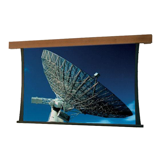
Draper Artisan Series Instrucciones de instalación y funcionamiento - Página 2
Navegue en línea o descargue pdf Instrucciones de instalación y funcionamiento para Pantalla de proyección Draper Artisan Series. Draper Artisan Series 2 páginas. Electric projection screen 220 v
También para Draper Artisan Series: Instrucciones de instalación y funcionamiento (2 páginas)

220V Artisan Projection Screen by Draper
Tab-Tension Adjustment Procedure
Draper's Tab-Tensioning System is factory-set, and under normal
circumstances will not require field adjustment. If, however, you notice
wrinkles, waves or other indications that the tensioning cables need to
be adjusted, follow the procedure below.
1 Determine which side requires adjustment.
2 Secure dowel with one hand.
Caution: Do not touch or bend surface.
3 Using Phillips-head screwdriver, depress
spring-loaded adjustment screw and slowly
turn clockwise to tighten tension, or
counterclockwise to loosen tension. The
screw adjusts in ¼ turn increments. Adjust
only one increment (¼ turn) at a time.
4 If problem is not corrected, leave screen in position
for 24 hours to allow surface material to stretch into position.
5 If problem still is not corrected, repeat steps 2 and 3.
Single Station Control
CE Approved
Junction box at
left end of screen
Internal Screen Wiring
Blue-220v (Common)
Brown-220v (Down)
Black-220v (Up)
Green/Yellow (Motor Ground)
Control
switch
Dashed wiring
by installer
Low Voltage and Remote Control
Tensioning
Cable
Dowel
Please Note: Do not wire motors in parallel.
Multiple Station Control
Junction box at
left end of screen
Red
Red
Red
220v,
50 Hz.
220v, 50 Hz.
White or Blue-Common to screen & 110/220V AC Neutral
Red-to screen (directional)
Brown-to screen (directional)
Yellow-to 110/220V AC-Hot
Black-to 110/220V AC-Hot
Green/Yellow (Ground)
Dashed wiring by electrician
Low voltage wiring by others
Eye Port for IR Eye, RF Receiver or LED
Wall Switch. For more than one of
these, a splitter is required.
3 Button Wall Switch
DOWN - Black
COM - White
UP - Red
Aux Port for connecting additional LVC-III
modules (up to six total can be linked-
connect from Aux to Eye).
www.draperinc.com
A
B
D
Adjustment
Screw
Series E
Series V
*Add 29 mm to height if case is to be bevel style.
Wiring Diagrams
Not CE Approved
Internal Screen Wiring
Blue-220v (Common)
Brown-220v (Down)
Black-220v (Up)
Green/Yellow (Motor Ground)
Cap off with wire
nut & tape
Blue
Black
Blue
Black
Blue
Black
Dashed wiring
by installer
Internal Screen Wiring
White/Blue (Common)
Red 110/Black 220 (Up)
Black 110/Brown 220 (Down)
Green/Yellow
(Motor Ground)
STOP
Location of key
operated on-off
switch if furnished
STOP
Control
Switches
24v DC
(765) 987-7999
Case Dimensions
Fabric width + C
A
B*
127 mm
133 mm
305 mm
152 mm
162 mm
varies
See separate Serial Communica-
tion-RS232 Instruction sheet for
enabling RS232 with the MC1.
To
110/220V
Line
Page 2 of 2
C
D
152 mm
varies
MC1
