Draper Ropewalker Instrucciones de instalación y funcionamiento - Página 4
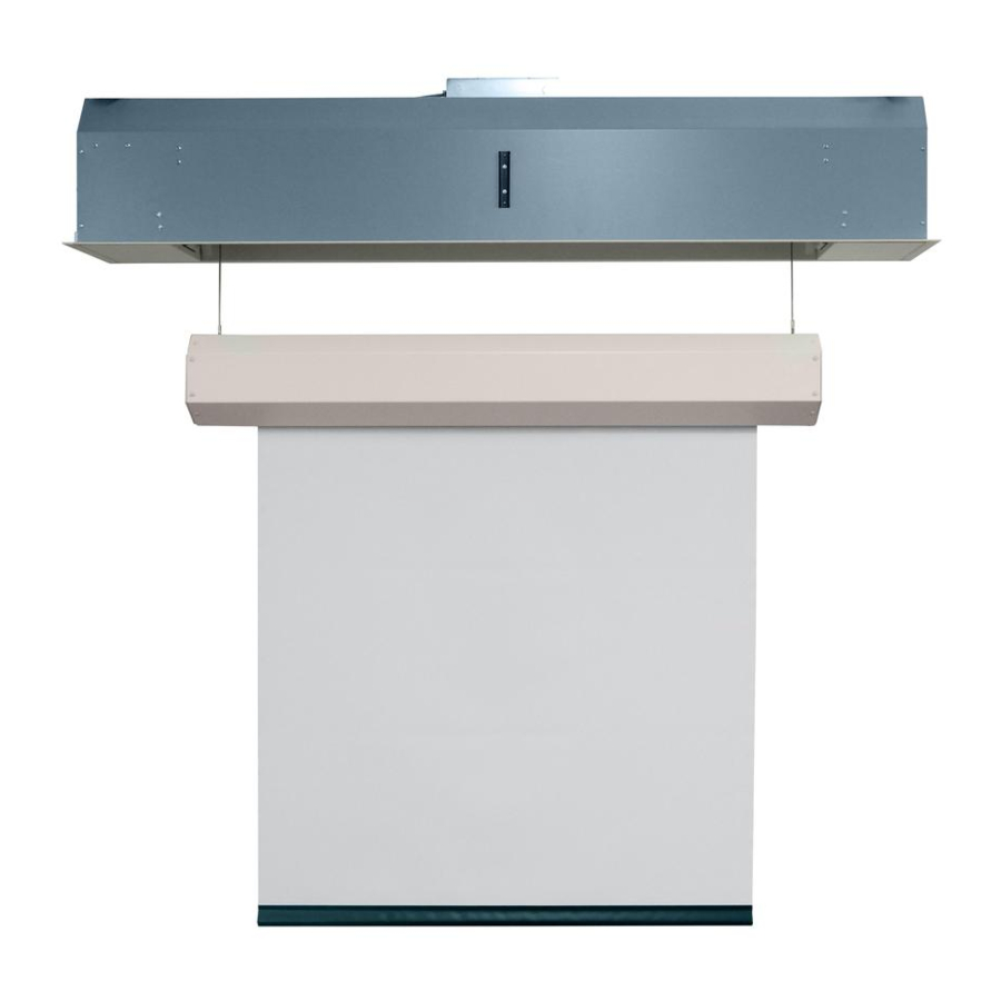
Navegue en línea o descargue pdf Instrucciones de instalación y funcionamiento para Pantalla de proyección Draper Ropewalker. Draper Ropewalker 8 páginas. Electric projection screen with cable drop

Ropewalker
Section 5 - Ropewalker Wiring
Standard Control Switch
Single switch requires a standard switch
box that measures 3"
(57mm)
optional control switch in accordance with
wiring diagram
Please Note: For 220V Single Station
Wiring see Page 8.
Figure 4
Low-Voltage Control for 110V Ropewalker
Low-Voltage Wiring
Black
Red
Com
Red
Black
Down
White
Blue
Up
Black
(L1)
White
(N)
Grn/Ylw
Location of key
operated on-off
switch (if furnished)
Programming RF Receiver Frequency
1. Open dip switch cover on end of Low-Voltage Controller
2. Locate the dip switch bank inside receiver and set the dip switches per the following chart, then close dip switch access
cover. A switch is in ON when in the down position
1
6
1
2 3 4 5 6 7
1
2
7
2
1
2
1
2
3
4
5
6
7
8
3
1
2
1
2
3
4
5
6
7
9
4
1
2 3
1
2
3
4
5
6
7
10
5
1
2
1
2
3
4
5
6
7
Attaching Optional Key Switch or Contact Closure Control to Low-Voltage Control
Low-Voltage Control Receiver is capable of having dual methods of operation.
It is possible to attach an optional Low-Voltage backup key switch, in addition to being operated with
an optional 99-Station RF Transmitter.
To connect the optional key switch, pull a three-conductor control wire between the switch location
and the Low-Voltage Control. The connections between the key switch and the terminal block
should be made per Figure 6.
on the outside of the receiver housing)
Key or contact closure must be held closed to operate Ropewalker to lower limit or closed position.
(SS-1R)
high x 2¼"
(76mm)
wide x 2½"
deep. Install
(64mm)
.
(Fig. 4)
Ropewalker Wiring
Brown (Down)
Red (Up)
White (Common)
Black (L1)
Grn/Ylw (Ground)
L1
NEU
Dashed wiring
by electrician
GND
To 110-120V Line
. Cover opens by loosening outer screw and rotating cover.
(Fig. 5)
(toward the mounting plate)
11
3
4
5
6
7
1
2
3
4 5
6
7
12
3
4
5
6
7
1
2
3
4 5
6
7
13
3
4
5
6
7
1
2
3
4 5
6
7
14
4
5
6
7
1
2
3
4
5
6
7
15
3
4 5
6
7
1
2
3
4
5
6
7
Single Station Control
Control
switch
Blue
Red
Location of key
operated on-off
switch (if furnished)
N
L1 To 110-120V Line
Low-Voltage Contact Closure Control Wiring
See wiring diagram at left.
1. Remove strain relief from the Low-Voltage Controller and replace with electical
conduit.
2. Connect Low-Voltage Controller to motor in accordance with wiring diagram.
3. If RF Remote included, program frequency of receiver by following steps below.
Please Note: For 220V Low-Voltage Wiring see page 8.
.
16
21
1
2
3
4
5
6
7
1
17
22
1
2 3
4
5
6
7
1
18
23
1
2
3
4
5
6
7
1
19
24
1
2
3
4
5
6
7
1
20
25
1
2
3
4
5
6
7
1
(located
Internal Screen Wiring
White (Common)
Brown (Down)
Red (Up)
Black (L1)
Grn/Ylw (Ground)
Single gang box (by others)
Min. 4" x 2
1
/
" x 1
7
/
" deep
8
8
(102x54x48mm)
Black
Dashed wiring
by electrician
Figure 5
2
3
4
5
6
7
2
3
4
5
6
7
2
3
4
5
6
7
2
3
4
5
6
7
2
3
4
5
6
7
Hole
Plug
Figure 6
Terminal
Strip Inside
page 4 of 8
Dipswitch
Access
Cover
