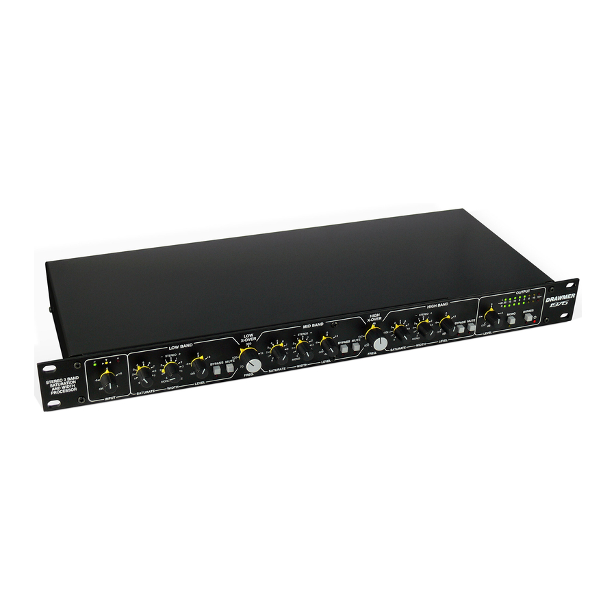
Drawmer 1976 Manual del usuario - Página 4
Navegue en línea o descargue pdf Manual del usuario para Hardware informático Drawmer 1976. Drawmer 1976 13 páginas. Stereo 3 band saturation and width processor

The 1976 is designed for standard 19" rack mounting and
occupies 1U of rack space. Avoid mounting the unit directly
above power amplifiers or power supplies that radiate
significant amounts of heat and always connect the mains
The 1976 unit will be supplied with a power cable suitable for domestic power outlets in your country. For your own safety,
it is important that you use this cable to connect to the mains supply earth. The cable must not be tampered with or
modified.
The power supply socket has an integral fuse drawer containing the power fuse of the same value, to suit the mains
voltage for which the unit has been supplied. Removal of the drawer is only possible with the power cord removed. The
fuse should never blow under normal operation. If the fuse is suspected of having blown, then a fault will have occurred
and this fault condition should be inspected by a qualified service engineer. When replacing the fuse, always comply with
the Safety Instructions.
If the unit is to be used with a mains input operating voltage different to that for which the unit is supplied, the following
procedure must be carried out by a technically competent person, (see following diagrams)
1: Disconnect the unit from the mains.
2: Using a number 1 size pozidrive
screwdriver, remove the seven self
-tapping screws that retain the top cover. Tw
screws are f ound along each
side; two along the top edge at the rear;
and the upper central screw on the front
facia panel.
3: Slide the voltage change-over switch
(S11) until the correct (or nearest) mains
input voltage is visible on the switch
actuator.
(see fig.2)
For con versi on to 115Volt AC
(previously set to 230Volt AC).....
4a: Exchange the 160mA fuse below
the mains socket for a similar type rated
at 315mA
For con versi on to 230Volt AC
(previously set to 115Volt AC).....
4b: Exchange the 315mA fuse below
the mains socket for a similar type rated
at 160mA
In all cases:
5: Replace the top cover using the seven
screws.
6: Re-connect to mains power source.
4
INSTALLATION
earth to the unit. Fibre or plastic washers may be used to
prevent the front panel becoming marked by the mounting
bolts. It is also advisable to leave space above the unit to
allow the heat to dissipate.
POWER CONNECTION
Voltage Selector
Switch located here
DRAWMER 1976 O
PERATOR'S
fig.2 The Voltage Selector Switch
fig.3 The Location of the Fuse
M
L
ANUA
Fuse
