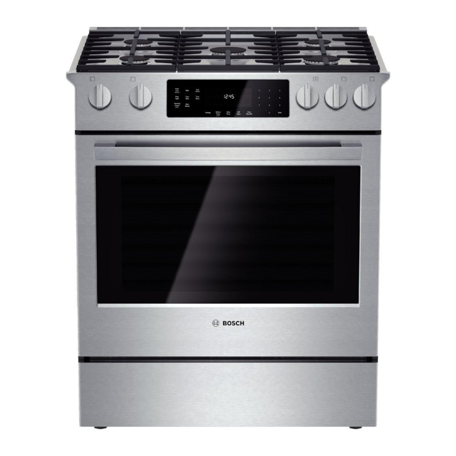
Bosch Vision 800 Series Manual de servicio - Página 42
Navegue en línea o descargue pdf Manual de servicio para Horno Bosch Vision 800 Series. Bosch Vision 800 Series 43 páginas. Gas slide-in ranges
También para Bosch Vision 800 Series: Manual de instrucciones (40 páginas), Dimensiones y especificaciones (2 páginas), Manual de instalación (6 páginas), Manual de instrucciones de instalación (28 páginas), Manual de servicio (36 páginas)

58300000202443_ARA_EN_C
7.4
Wiring Diagrams and Schematics
The wire color key (Table 11) and element strip diagrams are shown
below. For schematics, please refer to the Built-in Oven Service
Guide, which can be found on QuickFinder or attached to the control
module access cover in the upper oven plenum.
7.4.1
Wire Color Key
BK
Black
BN
GN
Green
GR
RD
VT
Red
YE
Yellow
BN/WH
OR/BK
Orange/Black
VT/WH
Table 11 Wire color key
7.4.2
Strip Diagrams
Figure 41 Upper / Single oven element strip diagram
Copyright by BSH Home Appliances Corporation
This material is intended for the sole use of BSH authorized persons and may contain confidential and proprietary information. Any unauthorized review, use, copying, disclosure, or distribution in any format is prohibited.
Brown
BU
Blue
Gray
OR
Orange
WH
Violet
White
Brown/White
BU/WH
Blue/White
Violet/White
YE/BK
Yellow/Black
1901 Main St ▪ Suite 600 ▪ Irvine, CA 92614
JANUARY 2018
Figure 42 Lower oven element strip diagram
Service Manual for Bosch 800 Series Built-in Wall Ovens
Page 42 of 43
800 944-2904
