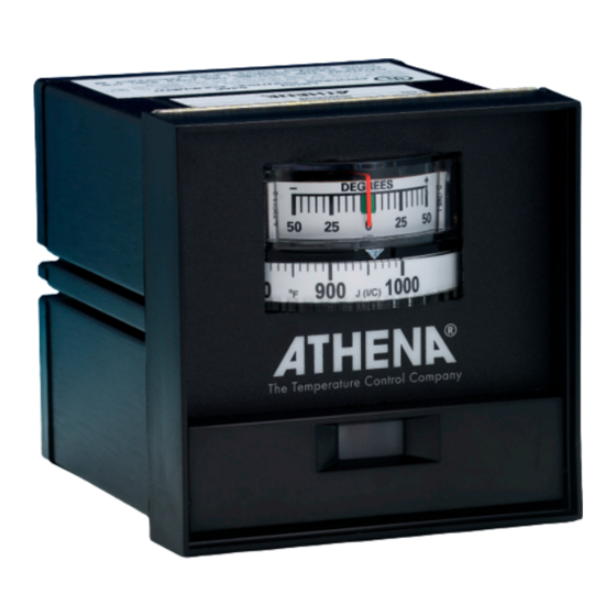
Athena 2000 Series Manual de instrucciones - Página 12
Navegue en línea o descargue pdf Manual de instrucciones para Controlador de temperatura Athena 2000 Series. Athena 2000 Series 16 páginas. Temperature/process controller
También para Athena 2000 Series: Manual de instrucciones (20 páginas)

Before you call, please look at this section to see if your question is covered here. If you do call for technical
assistance, be ready to supply the following information:
•
Troubleshooting
•
•
•
NOTE: Fuse blowing
is not caused by the
controller. Blown fuses
are caused by shorts
Symptom.
in the heater circuit,
and must be corrected
light, no meter deflection
to prevent damage to
the controller.
Probable Cause.
- No line voltage input
- Open PC board to back- plate connector
(defective connector)
- Open power transformer
Symptom.
nulls at ambient
Probable Cause.
- External backplate jumper missing (all
models except "S" and "F")
- Defective relay
- Open heater or heater circuit wiring
Symptom.
scale positive, no heat
Probable Cause.
- Open thermocouple or T/C wiring
Symptom
light stays on
Probable Cause.
- Thermocouple connections reversed
- T/C lead wires shorted between T/C and
control
Symptom. Full output, no control.
Output light goes off. Meter goes
upscale
Probable Cause.
- Relay contacts welded closed
Symptom
differs from setpoint when read with
an external pyrometer. Deviation meter
nulls and process is stable.
Probable Cause.
- T/C lead wires shorted close to process
- Wrong type of T/C being used, etc.
- Standard electrical wiring being used in
place of T/C wire
- Gradient error.
12
complete model number of controller
symptoms of the problem
unusual events, if any, that preceded the problem
remedies you have already tried
Controller dead. No output
No output, step 1 ok, meter
No output, meter reads full
Full output, no control. Ouput
Process control temperature
Check -
Verify 120/240 Vac, 50/60 Hz input voltage. Check
heater for shorts. Look for open breakers or open external
fuse. Remove input power. Check continuity through power
transformer primary. With ohmmeter, read between pins: 8
and 9 for 225 or 450 ohms +/-10% and 8 and 10 for 680 or
1000 ohms +/-10%
Corrective Action
- Replace heater, if shorted
- Restore power
- Replace either power transformer or backplate connector
Check -
If no readings in either step above, remove controller
from housing and repeat resistance measurements as above,
but directly on PC board lands corresponding to pins 8, 9, and
10. Correct readings indicate open PC board to backplate
connector problem. Incorrect readings indicate power
transformer problems.
Visually inspect relay contacts. Heater continuity and wiring
Corrective Action
- Install jumper
- Replace relay if contacts are worn or dirty
- Replace open heater, correct defective wiring
Check -
T/C continuity. Disconnect T/C connections from
instrument. Measure T/C circuit resistance. Ohmmeter should
read 100 ohms or less.
Corrective Action
- Replace T/C. Correct defective wiring
Connection polarity. T/C wires are color-coded. Red
Check -
is the negative (-) lead. (for U.S.A.) T/C lead wiring.
Corrective Action
-
Connect correctly
-
Repair or replace
Check -
Disconnect power and load. Measure resistance
between pins 12 and 13. Should read infinity.
Corrective Action -
If resistance reading is near 0 ohms,
replace relay.
Check T/C lead wires at back of probe Wire color
Check -
indicates type of T/C
- Verify type of wire
Corrective Action
- Replace defective wiring
- Install correct T/C for temperature range of instrument. See
instrument serial number tag for T/C type.
- Run only T/C wire between process and controller.
- Use electronic indicator in parallel with suspect instrument's
T/C input
