ATI Audio DA206 Manual de funcionamiento y mantenimiento - Página 3
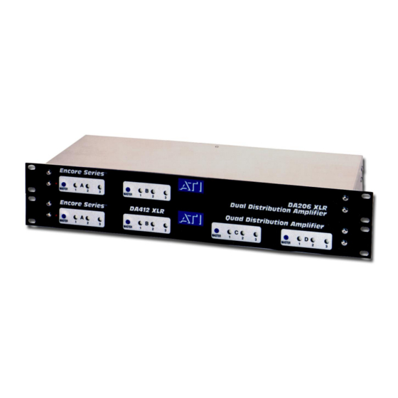
Navegue en línea o descargue pdf Manual de funcionamiento y mantenimiento para Amplificador ATI Audio DA206. ATI Audio DA206 5 páginas. Analog audio
distribution amplifiers
También para ATI Audio DA206: Manual de funcionamiento y mantenimiento (6 páginas)

INSTALLATION
MOUNTING
Your DA is designed for rack mounting on standard EIA 1 3/4-inch centers. Each unit
dissipates approximately 10 watts and is designed for use in an office environment. Avoid
excessive heat buildup (such as might be due to nearby power amplifiers in unventilated
racks) to ensure maximum component life.
WIRING
AUDIO CONNECTIONS
XLR type inputs and outputs are wired with pins 2 as Hi and pins 3 as Lo. Pin1 (shield) of
all input and output connectors are permanently grounded in accordance with the latest
AES recommendations. The pin1 grounds are routed via a large low impedance ground
path directly to the chassis separately from any audio ground paths. Internal circuit
ground is also connected to the chassis for shielding through an independent path. AC
ground (green wire) is also separately grounded to chassis. Active balanced outputs
require a reference ground connection to the receiving device for proper operation. This
ground is carried through pin1. If the pin1 shield ground is not carried through to the
receiving device, the AC ground may complete this ground, rack frame or studio ground
system. Noisy grounds require excellent common mode rejection in the receiving device
for quiet system operation.
We have taken measures to keep RFI out of your Encore Series DA including split and
bypassed input networks, beaded, bypassed and isolated power inputs, nonconcentric
wound, semi-toroidal power transformers, double ground plane PC boards and a nice
enclosure to keep rain and snow off the circuit boards. However, in difficult broadcast
applications, the RF shielding and suppression system can be no better than the ground
system into which it is trying to dump the unwanted RF.
For optimal product
performance, be sure to have a good grounding system
ADJUSTMENTS
The Master and individual output level controls should all be set close to 2 o'clock to
provide nominal +4dBm outputs for a nominal +4dBu input. These settings allow +6/-
16dB output adjustment range around nominal, which will allow outputs of +10 to -12dBm
to be set. In addition the Master gain has +10dB to OFF adjustment range to compensate
for input level variations from -6dBu to input clipping at +24dBu.
Changing the position of the input gain compensates for lower level inputs setting jumper
plugs (P2, P3, P8, P9). These plugs add 14 or 24dB of extra gain to permit nominal inputs
of -20dBu and minimum inputs as low as -30dBu for +4dBm out.
The input paralleling jumper plugs (P4 & P5, P6 & P7, P10 & P11) are located under the
hood just behind the input XLR connectors. They must be used in pairs (e.g. P4 & P5
together) to properly jumper HI & LO input lines. These jumper plugs let you use a DA412
as a Quad 1x3, Stereo 1x6 or a Mono 1x12 DA.
Audio Technologies Inc. | 154 Cooper Road #902 | West Berlin, NJ 08091 | Voice 856-719-9900 | Fax 856-719-9903 | www.
audio.com
