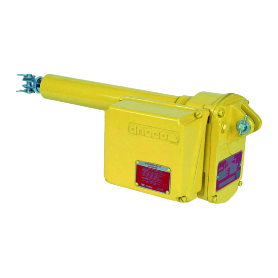
Andco Eagle Manual de instalación - Página 2
Navegue en línea o descargue pdf Manual de instalación para Controlador Andco Eagle. Andco Eagle 12 páginas.

3.0 Installation Requirements
SERVICE PERSONEL
Service operators must be licensed/trained and authorized before
being allowed to perform maintenance on the actuator.
Verify that the supply voltage to the actuator matches the voltage
on the nameplate (33) on the gear compartment cover (21).
CONDUCTOR TEMPERATURE RATING
All conductors used for field wiring connections to the actuator
shall carry a rating for a minimum temperature of 90°C.
Single person lift could cause injury.
Use assistance when moving or lifting.
1.
To prevent premature wear of the drive nut (7)
or extension rod seal/wiper (2), verify that the
alignment between the actuator mounting support
and the driven equipment places no side loading on
the extension rod (6) at any point throughout the full
stroke length. Refer to Figure 2 on page 7.
2.
Do not hammer or gouge the outside surface of
the extension rod (6). This may damage the plating
integrity or cause surface irregularities which can
damage rod seals.
3.
Face flange or trunnion mounted:
a. Position the body tube adapter (57) to the desired
orientation.
2
WARNING
PPE
Approved Personnel Protective
Equipment for the site must
be worn.
CAUTION
BURN HAZARD
Possible hot surface. Keep hands
clear of surface. Allow surface
to cool before performing any
maintenance.
WARNING
MOVING PARTS
Internal moving parts. Pinch
point hazard. Keep hands clear
during operation.
CAUTION
CAUTION
VOLTAGE SUPPLY
CAUTION
CAUTION
LIFTING HAZARD
b. Verify that the pins of the trunnion mounting
configuration are parallel with the clevis pin.
c. Tighten the nut and bolt arrangement of the body
tube adapter to 50-55 ft-lbs. of torque.
4.
For Clevis mounting: Verify the pins of the Clevis
bracket and for Clevis (29) are parallel.
5.
Apply a light film of lubricant to all pinned
connections.
NOTICE
In all mounting situations, the final trimming
adjustment of the actuator installation is ±1/8 inch.
6.
After Installation the actuator length can be
adjusted +/-1/8 inch
a. Loosen the jam nut (28).
b. Turn the Clevis (29) clockwise to decrease or
counter clockwise to increase the actuators installed
length.
CAUTION
Because the thread grip is limited, make sure the clevis (29) is
engaged by a minimum of four threads and that it does not contact
the drive screw (4) when the extension rod (6) is fully retracted.
7.
Upon completion of all mounting operations verify
that the jam nut (28) is tight, and that all cotter pins
have been secured.
8.
The actuator must be installed and wired in
accordance with all local electrical codes and the
most current edition of the National Electrical Code.
9.
Route the electrical conduit up into the actuator to
prevent internal condensation from running into the
limit switch compartment.
CAUTION
VOLTAGE SUPPLY
Verify that the supply voltage to the actuator matches the voltage
on the nameplate (33) on the gear compartment cover (21).
10. Keep limit switch compartment dry and clean.
To minimize the possibility of condensation damage,
it is suggested that moisture/gas tight conduit seals
be installed at the conduit connections.
11. Dust Ignition Proof Enclosure, Class II, Division 1,
Groups E, F & G.
Indoor and Outdoor Locations.
All actuators provided with dust-ignition proof
enclosures must have properly installed electrical
access covers to exclude ignitable amounts of dust.
When reinstalling these covers make sure the mating
seating surfaces and gaskets are clean and the
attachment bolts are securely tightened. If the
motor end bell pipe plug has been removed to adjust
the actuator, the pipe plug must be reinstalled tightly.
The actuators must be able to operate at full rating
without developing surface temperatures high enough
