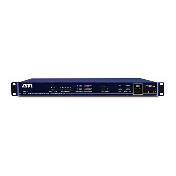
ATI Technologies DSA224-BNC Manual de funcionamiento y mantenimiento - Página 5
Navegue en línea o descargue pdf Manual de funcionamiento y mantenimiento para Amplificador ATI Technologies DSA224-BNC. ATI Technologies DSA224-BNC 8 páginas. Aes/ebu digital audio distribution amplifiers

OUTPUT DRIVERS
DDAxxx-XLR and DSAxxx-XLR units use the balanced, 110-ohm, transformer
coupled outputs and XLR type connectors shown on the referenced schematics.
DDAxxx-BNC and DSAxxx-BNC units use the alternative 75-ohm unbalanced
outputs to BNC coax connectors shown on the same schematics. The XLR
outputs are in full compliance with specification AES3-1992 and the BNC outputs
are in accordance with the recommendations of AES-3id-1995. RS-422
differential line drivers U1 and U2 (U5 and U6) provide a balanced drive for XLR
outputs of 8Vp-p, open circuit through 110-ohm source resistance to yield 4Vp-p
when loaded by a 110-ohm load. XLR outputs are transformer coupled for
ground isolation. Each side of the differential line driver output is used to
separately drive a 75-ohm capacitor coupled BNC output. Each BNC output
provides 4Vp-p open circuit thru 75 ohms for a loaded output of 2Vp-p. Although
the two sides of a differential line driver are out of phase with each other there is
no phase difference in the recovered audio since the AES/EBU digital data is
defined only by the presence or absence of transitions. It makes no difference
whether those transitions are hi to low or low to hi.
REFERENCE OSCILLATORS AND POWER SUPPLIES
U10 generates a 6 MHz reference frequency input to U8 (U17) for determining
the incoming frame (sample) rate. The oscillator is counted down in U11, 12, 15
and 16 to provide a synchronized display reset pulse every 3 seconds. U21
generates a precision 2.5VDC reference for the equalizer circuit. U7 and U13
provide regulated and quiet +/-5VDC for all circuits. Power transformer primary
windings are paralleled for 115VAC or wired in series for 230VAC. Jumpers E1
allows field modification if necessary.
INSTALLATION
LOCATION
To avoid addition of jitter (timing variations) to the digital bitstream, which could
cause noise and distortion in the recovered audio, avoid locating the DDA or
DSA in close proximity to a high energy, high frequency switching type power
supply or a power amplifier that utilizes a switching supply. If possible, do not
power both devices from the same AC power line.
Expensive components start to die at internal temperatures above 70° C (158° F).
We recommend that you maintain rack temperatures below 50° C (122° F) to
prevent excessive internal temperature buildup. This is another good reason not
to mount the DDA or DSA directly above that 500W power amplifier. Don't force
the DDA to support the weight of 28 coax or 16 XLR cables (especially when you
drop that 500W power amplifier on the cable bundle), support the cables.
Audio Technologies Inc.
• Tel: 856-626-3480
•
Fax: 856-504-0220
•
www.
audio.com
