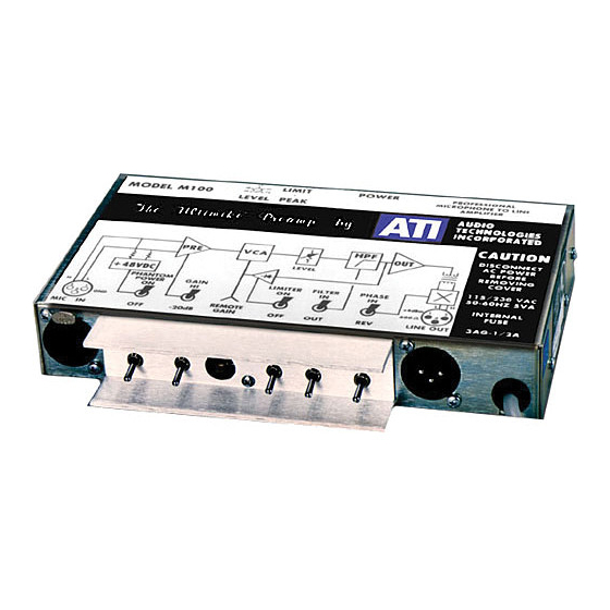
ATI Technologies M100 Manual de funcionamiento y mantenimiento - Página 6
Navegue en línea o descargue pdf Manual de funcionamiento y mantenimiento para Amplificador ATI Technologies M100. ATI Technologies M100 8 páginas. Ati ultimike m100 microphone amplifier operating and maintenance manual
También para ATI Technologies M100: Manual de funcionamiento y mantenimiento (9 páginas)

COMMON MODE REJECTION
Replacement of R6, R7, R8, R9, R62, C11, or C12 will require readjustment of R27 to
maintain maximum common mode rejection (CMR). To set R27, apply 10 Vrms at 60
Hz between ground pin 1, pin 2, and pin 3 (tied together) of XLR input J1. Measure
output (at J2 pins 2 to 3) and adjust R27 for null. A 90 dB CMR is attainable but may be
difficult to measure without a tuned voltmeter.
DISTORTION
Replacement of R36, R37 R38, R39, and R40 or output transformer T2 will require
readjustment of R40. Apply sufficient 20 Hz signal to the input with the gain switch at
–20 dB and the gain control set to 12 o'clock to drive the loaded output to +20 dBm.
Measure Total Harmonic Distortion (THD) at the output and adjust R40 for the best null.
If you cannot detect a good null, your audio generator may well have more internal
distortion at 20 Hz than even the untrimmed contribution of the M100, which is typically
less than .25%. When properly set, using superior test equipment such as Amber or
Audio Precision, distortion measurements should be limited only by residual white noise
to levels of .03% across the audible band.
GENERAL
Power supply voltages are + and – 16 VDC nominal. IC output DC voltages under no
signal, shorted input conditions should read 0 VDC at A1 and A2, pins 1 and 7, A3-7,
A4-1 and 7 and A5, pin 1 and 6. A3 pin 1 should read within the range of + to –10 VDC
and a 28 Vp-p square wave should be visible with an oscilloscope at A5, pins 8 and 14.
Deviations of more than .1 VDC from the 0 VDC nominal is an indication of IC or circuit
problems. Ten years from now, we recommend replacing all aluminum electrolytic
capacitors. Keep 250 Watt soldering guns out of the M100.
MODIFICATIONS
230 VAC OPERATION
The M100 is wired for 115 VAC, 50/60 Hz operation unless otherwise requested at the
time of ordering. It can be modified for 230 VAC use by removing W1 and W3 and
inserting a jumper wire in W2.
Audio Technologies Inc. | 154 Cooper Road #902 | West Berlin, NJ 08091 | Voice 856-719-9900 | Fax 856-719-9903 | www.
audio.com
