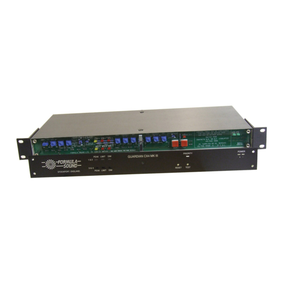
Formula Sound GUARDIAN CX4 MK II Manual del usuario - Página 6
Navegue en línea o descargue pdf Manual del usuario para Accesorios Formula Sound GUARDIAN CX4 MK II. Formula Sound GUARDIAN CX4 MK II 8 páginas. Priority interface and sound level control
Gain
Frequency Response
Distortion THD @ 1KHz
Noise
Inputs
Connector type
Input impedance
Max input level
Outputs
Connector type
Max O/P level
Controls
1
2
3
4
5
6
7
8
9
10
11
12
Priority input
Connector type
Set to Mic
Set to Line
Visual indicators
Control input
connections
Security loop
Remote indicator outputs
Outputs will drive LED's without series resistors (or suitable solid state relays to drive mains voltage indicators).
Dimensions
Finish:-
Power
GUARDIAN CX4 MKIII TECHNICAL SPECIFICATION
Normal operation, unity gain +0dB -1dB
20Hz - 20KHz + 0.5dB -1dB
O/P +20dBU <.015% (Typically .007%)
< -90dBU EIN
Balanced
XLR
> 30K Ohms
+22dBU
Electronically balanced
XLR
+22dBU into 600R load
Situated behind removable front panel (counting from the left)
Priority input level all channels.
Priority input level channels 3&4 (allows chans 3&4 to be lower than chans1&2)
Attenuation channels 1&2. Range 0dB to –60dB (factory setting –20dB)
Attenuation channels 3&4. Range 0dB to –60dB (factory setting –20dB)
Peak threshold 1&2 setting of peak limiter above the average limit threshold
Limit threshold 1&2 (average) adjustable range -20dBU to +22dBU
DIM limit threshold 1&2 limit threshold
Peak threshold 3&4 setting of peak limiter above the average limit threshold
Limit threshold 3&4 (average) adjustable range -20dBU to +22dBU
DIM limit threshold 3&4 limit threshold
Reset momentary action push button (adjacent jumper position determines
the type of reset - auto or manual.
Test momentary action push button. (For set-up and testing)
Internally selectable Mic – Line (18V Phantom power available on a jumper).
XLR in and out
Low impedance. Balanced. Max gain 70dB
10K Balanced. Max I/P level +30dBU
2 x Green LED's.
Power -
2 x Red LED's.
Limit
2 x Amber LED's.
Peak -
2 x Red LED's.
Dim -
Priority override -
Red LED.
Pins 1 & 2 18V - 24V DC ( Voltage mode)/Isolated switch contacts (Switch Auxiliary
2 x 6 Way screw terminal connector mode)
Pins 3&4 channels 1&2, Pins 5 & 6 channels 3&4. Break to trigger
A & G N/C
B & H Dim LED +VE
D & J Peak LED +VE
E & K Priority LED +VE F & L Common 0VE
19" rack mounting. 1RU, Width 482mm (19"), Depth 206mm (8.1"), Height 44mm (1.75")
Front - and Rear panels- Black anodised aluminium with silver notation which will not rub off in
use. Case - black plastic coated steel.
IEC Connector 220 - 240V AC. Mains Fuse 250mA Anti Surge (slow blow)
110 – 120V AC. Mains fuse 500mA Anti Surge (slow blow)
C & I Limit LED +VE