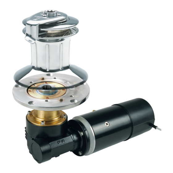
Andersen E1 Manual del producto - Página 11
Navegue en línea o descargue pdf Manual del producto para Cabrestantes Andersen E1. Andersen E1 18 páginas. Single speed electric motor unit, 12v & 24v
También para Andersen E1: Manual del producto (18 páginas)

ELECTRICAL CONNECTION DIAGRAM
58/62 ST E1 SINGLE SPEED 12V/24V
PUSH BUTTON
DETAIL A
4
4
2
5
E1 Single Speed Electric Motor Unit, 12V & 24V
To Suit Self-Tailing Winch Sizes 58,62
WARNING
3
1
3
1
6
Positive (+) motor terminal must be
connected to Positive (+) battery terminal.
Negative (-) motor terminal must be
connected to Negative (-) battery terminal.
If polarity is reversed the motor controller
internal fuse will blow and need to be
replaced. See page 12 for instructions.
DETAIL A
STANDARD CONNECTION
PUSH BUTTON CABLE
MOTOR CABLE
1. Blue
= 1. Brown
3. Blue Black = 3. Green
4. Red
= 4. Yellow
Wires are marked with numbered sleeves
Push button cable
1. Blue
= Switch
3. Blue Black = Ground
4. Red
= LED
Motor cable
1. Brown = Switch 1
2. White = Switch 2 (used for 2 speed motors only)
3. Green = Ground
4. Yellow = LED
5. Grey
= Ratiometric current output
6. Pink
= Low current cutout
p11
CIRCUIT BREAKER
BATTERY (12V or 24V)
WINCH MOTOR
