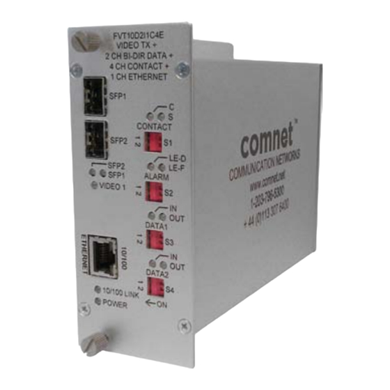
Comnet FVT10D2I1C4E Manual de instalación y funcionamiento - Página 5
Navegue en línea o descargue pdf Manual de instalación y funcionamiento para Media Converter Comnet FVT10D2I1C4E. Comnet FVT10D2I1C4E 10 páginas. 10-bit digitally encoded video

INSTALLATION AND OPERATION MANUAL
FIGURE 6 – DATA SWITCH POSITIONS
The mode for each data channel is configured using a set of two switches labeled DATA1 (S3) and DATA2 (S4), located on the front panel of the unit.
FIGURE 7 – RJ-45 PIN OUT
PIN # RS232
1
NC
2
RS232 – OUTPUT
3
NC
4
RELAY OUT
5
RELAY OUT
6
RS232 – INPUT
7
GND
8
+5V (BIAS)
NC = No Connection
TECH SUPPORT: 1.888.678.9427
DATA1 (S3)
DATA2 (S4)
1
2
1
2
ON
ON
ON
ON
ON
OFF
OFF
ON
OFF
ON
OFF
ON
OFF
OFF
OFF
OFF
RS422
RS422 OUTPUT –
RS422 OUTPUT +
RS422 INPUT +
RELAY OUT
RELAY OUT
RS422 INPUT –
GND
+5V (BIAS)
Resulting Mode
RS232
RS422, Bi-Phase or Manchester
RS485 2-Wire, Sensornet
RS485 4-Wire
PIN # Wire Color
Data Connections
1
Blue
DATA OUT –
2
Orange
DATA OUT +
3
Black
DATA IN +
4
Red
RELAY OUT
5
Green
RELAY OUT
6
Yellow
DATA IN –
7
Brown
GND
8
White
+5V (BIAS)
RS485 2-Wire
NC
NC
RS485 INPUT +
RELAY OUT
RELAY OUT
RS485 INPUT –
GND
+5V (BIAS)
FVT/FVR20D2I1C4E
RS485 4-Wire
RS485 OUTPUT –
RS485 OUTPUT +
RS485 INPUT +
RELAY OUT
RELAY OUT
RS485 INPUT –
GND
+5V (BIAS)
INS_FVT/FVR20D2I1C4E_REV- 06/22/12 PAGE 5
