AirTech Air+ PIV Instrucciones de instalación y puesta en marcha - Página 7
Navegue en línea o descargue pdf Instrucciones de instalación y puesta en marcha para Ventilador AirTech Air+ PIV. AirTech Air+ PIV 16 páginas. Positive input ventilation unit
También para AirTech Air+ PIV: Instrucciones de instalación y puesta en marcha (16 páginas)

DIFFUSER GRILLE:
The heater unit must not be located directly below a socket.
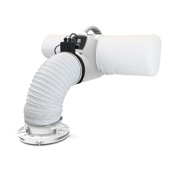
The diffuser must be carefully sited to ensure the maximum effectiveness of the
system. It should be fitted in the ceiling of a common area, ideally above the landing
so that the incoming air can reach all the rooms.
Cut the flexible ducting to a suitable length, where possible stretch the ducting to
its maximum extent and ensure that there is one continuous smooth bend to the
diffuser. The ducting must remain a minimum of 1m in length.
Remove the loft insulation from the location of the diffuser and cut a 240-260mm dia
hole in the ceiling.
Ensure the four locking tabs are folded in and then push the spigot in to the hole.
Holding the diffuser in place; screw the four screws until the locking tabs are
holding the diffuser tight against the ceiling. Fig. 5 It is important not to over
tighten these screws as this may warp the diffuser.
Fit the free end of the flexible ducting to the diffuser spigot using the worm drive
clip supplied.
The diffuser should not be situated within 1m of a smoke detector, however if this is
not possible the AIR+ PIV has provisions to blank off the airflow for up to two
quadrants of the diffuser. Two blanking plates are provided; these should be pushed on
to the support struts inside the diffuser as required. This should be done before the
diffuser is installed in the ceiling as when the screws are tightened down the plates
can no longer be removed. Fig.6
Blanking off one side reduces the flow by about 6%, but blanking off two sides reduces
the flow by about 20% and so if two sides are blanked off then you should consider
increasing the fan speed to maintain the appropriate airflow.
Fig. 5.
Fig. 6.
7
