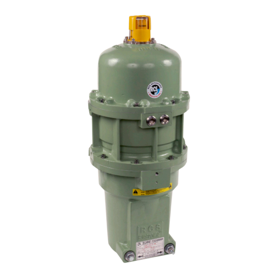
Dresser Surepowr Sure 150 Manual de instalación - Página 13
Navegue en línea o descargue pdf Manual de instalación para Controlador Dresser Surepowr Sure 150. Dresser Surepowr Sure 150 16 páginas. Rcs actuators

6. Operation
Power On: The electric motor drives the gear train,
which in turn winds the spring and turns the device.
An internal limit switch de-energizes the motor and
energizes the brake, which holds the return spring
and device in position.
Power Off: When the current is interrupted by either
a control signal or a power failure, the return spring drives
the device to its original position.
NOTICE:
To prolong cycle life, it is recommended
that the actuator be driven electrically in both directions
for normal operation.
Thermal Overload
The internal thermal overload switch de-energizes
the motor and prevents overheating of the motor
windings due to excessive operation, stalling or high
ambient temperatures. De-energizing the motor due
to thermal overload will result in actuator spring-driving
to the power loss position.
Duty Cycle
The maximum duty-cycle to be expected without
interruption by thermal cut-off at an ambient
temperature of 65C° (150°F) is 25 percent (three
"OFF" times for every one "ON" time).
Optional Manual Override
The optional Manual Override can be used to position the
actuator when no power is available.
Failure to respect these Notices may result in damage
to the device:
NOTICE:
Do not engage Manual Override while power
is applied to the actuator.
NOTICE:
Do not disengage Manual Override while it is under load.
NOTICE:
Do not apply power to the actuator while
Manual Override is engaged.
Engage Manual Override by releasing the latching
lever and rotating the handle 90 degrees. It is helpful to
rotate the hand wheel back and forth slightly during this
operation to assist in gear tooth engagement. After the
handle has been latched into the new orientation, rotate
the hand wheel to position the actuator. Take care not
to run the actuator tightly into either of the travel stops
as this may cause damage to the actuator. Position the
actuator in its spring fail position before disengaging
Manual Override. Do not disengage Manual Override
while the hand wheel is under load.
7. Maintenance
Only qualified, certified and properly trained personnel
shall conduct actuator maintenance.
The gear train is permanently lubricated at the factory
for the average life of the actuator. No further attention is
required.
Commissioned actuators should be checked routinely for
damage to paint finish, and touchup paint can be applied
where necessary to prevent corrosion.
Actuators that are infrequently operated should be tested
every six months to ensure they are ready to operate.
The actuator shall be set to fail safe or pre set position
before starting any maintenance work. Turn off the
power if it is not required for maintenance work. Remove
pre load when necessary, if in doubt, contact the
manufacturer.
Steps in removing spring pre-load.
1.
Uncouple the actuator from the driven object.
2.
Apply electric power to the actuator brake.
3.
Back out motor end hard stop. It will not come
out completely. It is designed not to come out
completely.
4.
Back out the spring end of hard stop.
5.
Turn off the power to the brake. The spring will
back drive motor and gear train.
6.
Use a wrench to rotate the output shaft back and fort
to ensure spring pre load is released.
Mounting Fasteners
For Mounting Fastener Specifications, refer to
the Installation section of this manual.
Six months after commissioning, and annually
thereafter, check fasteners between the actuator
and the driven device for tightness. If required,
tighten fasteners, being sure to apply the correct
specified torque. Failure to maintain specified torque may
compromise actuator operation.
Enclosure Cover Screws
For enclosure cover screw specifications and torque,
refer to the Installation section of this manual.
Six months after commissioning, and annually
thereafter, check the actuator cover screws for
tightness. If required, tighten screws applying the
WARNING
HIGH ENERGY HAZARD –
LOADED SPRING
Death or serious injury
could result.
Do not attempt to repair the
actuator unless properly trained
in specific repair methods for
this device.
13
